5-4
Troubleshooting Procedures
♦
Faulty LCD - Replace the cover-display assembly as described in Section 6 of
this manual.
♦
Low battery - Use a fully charged battery and/or plug in the AC adapter.
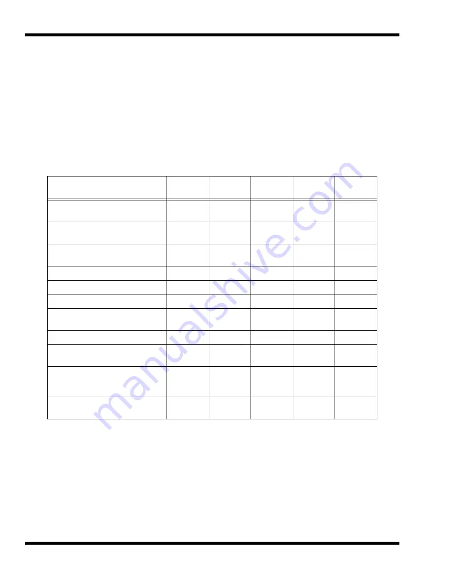
Table 5-1 contains fault isolation information for Display Problems on the notebook.
Symptoms are listed along the left side of the chart and the various Display FRUs are
listed along the top of the chart. Within the body of the table are the probabilities of
each of the FRUs causing that particular problem. For example, a single display line
on the screen is most likely caused by the LCD Panel or Display Cable; other
components have a low probability of causing the problem.
Table 5-1 Display Troubleshooting Guide
Problem Description
Inverter
Board
LCD
Panel
Display
Cable
Mother
Board
BIOS
Single line on LCD display (horizontal
or vertical)
Low
High
Medium
Low
Low
Multiple lines on display (horizontal or
vertical)
Low
Medium
Medium
Low
Low
Sections of the display are missing
characters
Low
Medium
Medium
Low
Low
Scrambled Display
Low
Medium
Low
Medium
Medium
Intermittent characters on display
Low
Medium
Medium
Medium
Low
Bright display, no visible characters
Low
Medium
Medium
Medium
Low
Brightness level fluctuating or display
blinking on/off
High
Low
Medium
Low
Low
Display goes dim over time
High
Medium
Low
Low
Low
Dim display but characters very
visible
Medium
Medium
Low
Low
Low
Very dark display and characters are
slightly visible when a light is directed
at surface of the display
High
Low
Low
Low
Low
Very dark display and no characters
are visible
Low
High
High
Medium
Low
Summary of Contents for Extensa 660 Series
Page 1: ...Maintenance Manual ExtensaTM 660 Series Notebook Computers 9813214 0001 Rev A February 1997 ...
Page 42: ......
Page 60: ......
Page 94: ......
Page 122: ......
Page 124: ...A 2 Schematic Diagrams Figure A 1 Motherboard PWB Logic Diagrams Sheet 1 of 23 ...
Page 125: ...Schematic Diagrams A 3 Figure A 2 Motherboard PWB Logic Diagrams Sheet 2 of 23 ...
Page 126: ...A 4 Schematic Diagrams Figure A 1 Motherboard PWB Logic Diagrams Sheet 3 of 23 ...
Page 127: ...Schematic Diagrams A 5 Figure A 1 Motherboard PWB Logic Diagrams Sheet 4 of 23 ...
Page 128: ...A 6 Schematic Diagrams Figure A 1 Motherboard PWB Logic Diagrams Sheet 5 of 23 ...
Page 129: ...Schematic Diagrams A 7 Figure A 1 Motherboard PWB Logic Diagrams Sheet 6 of 23 ...
Page 130: ...A 8 Schematic Diagrams Figure A 1 Motherboard PWB Logic Diagrams Sheet 7 of 23 ...
Page 131: ...Schematic Diagrams A 9 Figure A 1 Motherboard PWB Logic Diagrams Sheet 8 of 23 ...
Page 132: ...A 10 Schematic Diagrams Figure A 1 Motherboard PWB Logic Diagrams Sheet 9 of 23 ...
Page 133: ...Schematic Diagrams A 11 Figure A 1 Motherboard PWB Logic Diagrams Sheet 10 of 23 ...
Page 134: ...A 12 Schematic Diagrams Figure A 1 Motherboard PWB Logic Diagrams Sheet 11 of 23 ...
Page 135: ...Schematic Diagrams A 13 Figure A 1 Motherboard PWB Logic Diagrams Sheet 12 of 23 ...
Page 136: ...A 14 Schematic Diagrams Figure A 1 Motherboard PWB Logic Diagrams Sheet 13 of 23 ...
Page 137: ...Schematic Diagrams A 15 Figure A 1 Motherboard PWB Logic Diagrams Sheet 14 of 23 ...
Page 138: ...A 16 Schematic Diagrams Figure A 1 Motherboard PWB Logic Diagrams Sheet 15 of 23 ...
Page 139: ...Schematic Diagrams A 17 Figure A 1 Motherboard PWB Logic Diagrams Sheet 16 of 23 ...
Page 140: ...A 18 Schematic Diagrams Figure A 1 Motherboard PWB Logic Diagrams Sheet 17 of 23 ...
Page 141: ...Schematic Diagrams A 19 Figure A 1 Motherboard PWB Logic Diagrams Sheet 18 of 23 ...
Page 142: ...A 20 Schematic Diagrams Figure A 1 Motherboard PWB Logic Diagrams Sheet 19 of 23 ...
Page 143: ...Schematic Diagrams A 21 Figure A 1 Motherboard PWB Logic Diagrams Sheet 20 of 23 ...
Page 144: ...A 22 Schematic Diagrams Figure A 1 Motherboard PWB Logic Diagrams Sheet 21 of 23 ...
Page 145: ...Schematic Diagrams A 23 Figure A 1 Motherboard PWB Logic Diagrams Sheet 22 of 23 ...
Page 146: ...A 24 Schematic Diagrams Figure A 1 Motherboard PWB Logic Diagrams Sheet 23 of 23 ...
Page 147: ......


