Troubleshooting Procedures
5-17
5.5.4 Quitting PC-Doctor
To exit PC-Doctor, select the
Quit
pull down menu and then select the
Quit
option.
Note:
For additional information, access the
Online Reference Manual
for
PC-Doctor.
5.6 Board Level Troubleshooting Procedures
Figures 5-2 through 5-19 contain board-level troubleshooting procedures for the
Extensa 660 Notebook. Table 5-6 contains a diagram index to the troubleshooting
procedures:
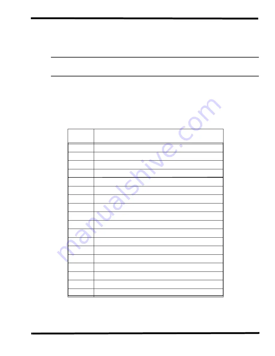
Table 5-6 Troubleshooting Flowchart Index
Figure
No.
Description
5-2
System Fails to Boot, Initial Checks
5-3
Memory Interface Troubleshooting Diagram
5-4
CRT Interface Troubleshooting Diagram
5-5
FDD Interface Troubleshooting Diagram
5-6
HDD Interface Troubleshooting Diagram
5-7
Keyboard Interface Troubleshooting Diagram
5-8
CD-ROM Interface Troubleshooting Diagram
5-9
Glidepad Interface Troubleshooting Diagram
5-10
DC/DC Converter Interface Troubleshooting Diagram
5-11
Battery Charger Interface Troubleshooting Diagram
5-12
LED Indicator Function Troubleshooting Diagram
5-13
Serial Port Function Troubleshooting Diagram
5-14
Suspend Function Troubleshooting Diagram
5-15
Cover Switch Function Troubleshooting Diagram
5-16
Cover Close Function Troubleshooting Diagram
5-17
External Keyboard Function Troubleshooting Diagram
5-18
PS/2 External Mouse Function Troubleshooting Diagram
5-19
Printer Port Interface Troubleshooting Diagram
Summary of Contents for Extensa 660 Series
Page 1: ...Maintenance Manual ExtensaTM 660 Series Notebook Computers 9813214 0001 Rev A February 1997 ...
Page 42: ......
Page 60: ......
Page 94: ......
Page 122: ......
Page 124: ...A 2 Schematic Diagrams Figure A 1 Motherboard PWB Logic Diagrams Sheet 1 of 23 ...
Page 125: ...Schematic Diagrams A 3 Figure A 2 Motherboard PWB Logic Diagrams Sheet 2 of 23 ...
Page 126: ...A 4 Schematic Diagrams Figure A 1 Motherboard PWB Logic Diagrams Sheet 3 of 23 ...
Page 127: ...Schematic Diagrams A 5 Figure A 1 Motherboard PWB Logic Diagrams Sheet 4 of 23 ...
Page 128: ...A 6 Schematic Diagrams Figure A 1 Motherboard PWB Logic Diagrams Sheet 5 of 23 ...
Page 129: ...Schematic Diagrams A 7 Figure A 1 Motherboard PWB Logic Diagrams Sheet 6 of 23 ...
Page 130: ...A 8 Schematic Diagrams Figure A 1 Motherboard PWB Logic Diagrams Sheet 7 of 23 ...
Page 131: ...Schematic Diagrams A 9 Figure A 1 Motherboard PWB Logic Diagrams Sheet 8 of 23 ...
Page 132: ...A 10 Schematic Diagrams Figure A 1 Motherboard PWB Logic Diagrams Sheet 9 of 23 ...
Page 133: ...Schematic Diagrams A 11 Figure A 1 Motherboard PWB Logic Diagrams Sheet 10 of 23 ...
Page 134: ...A 12 Schematic Diagrams Figure A 1 Motherboard PWB Logic Diagrams Sheet 11 of 23 ...
Page 135: ...Schematic Diagrams A 13 Figure A 1 Motherboard PWB Logic Diagrams Sheet 12 of 23 ...
Page 136: ...A 14 Schematic Diagrams Figure A 1 Motherboard PWB Logic Diagrams Sheet 13 of 23 ...
Page 137: ...Schematic Diagrams A 15 Figure A 1 Motherboard PWB Logic Diagrams Sheet 14 of 23 ...
Page 138: ...A 16 Schematic Diagrams Figure A 1 Motherboard PWB Logic Diagrams Sheet 15 of 23 ...
Page 139: ...Schematic Diagrams A 17 Figure A 1 Motherboard PWB Logic Diagrams Sheet 16 of 23 ...
Page 140: ...A 18 Schematic Diagrams Figure A 1 Motherboard PWB Logic Diagrams Sheet 17 of 23 ...
Page 141: ...Schematic Diagrams A 19 Figure A 1 Motherboard PWB Logic Diagrams Sheet 18 of 23 ...
Page 142: ...A 20 Schematic Diagrams Figure A 1 Motherboard PWB Logic Diagrams Sheet 19 of 23 ...
Page 143: ...Schematic Diagrams A 21 Figure A 1 Motherboard PWB Logic Diagrams Sheet 20 of 23 ...
Page 144: ...A 22 Schematic Diagrams Figure A 1 Motherboard PWB Logic Diagrams Sheet 21 of 23 ...
Page 145: ...Schematic Diagrams A 23 Figure A 1 Motherboard PWB Logic Diagrams Sheet 22 of 23 ...
Page 146: ...A 24 Schematic Diagrams Figure A 1 Motherboard PWB Logic Diagrams Sheet 23 of 23 ...
Page 147: ......


