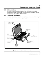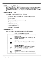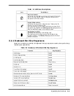
2-10
Installation
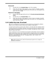
2.4.4 Installing an External VGA Monitor
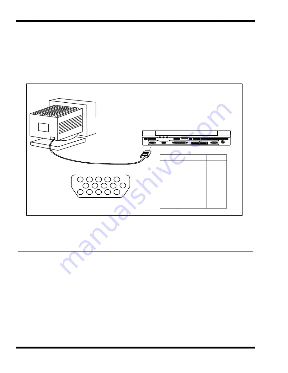
The notebook contains an external CRT port that can drive one of a variety of monitor
resolutions and colors as summarized in Table 1-9. The associated connector location
and pinouts are shown in Figure 2-7.
Figure 2-7 External VGA Pinouts
Use the following procedure to install an external monitor:
1.
Turn off power to both the notebook and monitor.
2.
Connect the 15-pin external VGA cable from the monitor to the VGA connector
on the notebook computer (refer to Figure 2-7).
3.
Power up the notebook computer first; then, turn on power to the monitor.
4.
Setup the notebook display mode for
LCD only
,
simultaneous LCD and CRT
or
CRT only
(under Windows 95, select the
Change Display Utility
; under
Windows for Workgroups, use the
WinMode Utility
).
5.
Install the correct driver, if required (refer to the Monitor Installation
Instructions supplied by the CRT vendor).
1
2
3
4
5
6
7
8
9
1 0
11, 12
1 3
1 4
1 5
RED VIDEO
GREEN VIDEO
BLUE VIDEO
NOT USED
GROUND
RED RETURN
GREEN RETURN
BLUE RETURN
NOT USED
GROUND
NOT USED
HORIZONTAL SYNC
VERTICAL SYNC
NOT USED
OUTPUT
OUTPUT
OUTPUT
INPUT
INPUT
INPUT
OUTPUT
OUTPUT
PIN
SIGNAL NAME
DIRECTION
EXTERNAL VGA CONNECTOR PINOUTS
1
2
3
4
5
7
8
9
1 0
6
1 1
1 2
1 3
1 4
1 5
Summary of Contents for Extensa 660 Series
Page 1: ...Maintenance Manual ExtensaTM 660 Series Notebook Computers 9813214 0001 Rev A February 1997 ...
Page 42: ......
Page 60: ......
Page 94: ......
Page 122: ......
Page 124: ...A 2 Schematic Diagrams Figure A 1 Motherboard PWB Logic Diagrams Sheet 1 of 23 ...
Page 125: ...Schematic Diagrams A 3 Figure A 2 Motherboard PWB Logic Diagrams Sheet 2 of 23 ...
Page 126: ...A 4 Schematic Diagrams Figure A 1 Motherboard PWB Logic Diagrams Sheet 3 of 23 ...
Page 127: ...Schematic Diagrams A 5 Figure A 1 Motherboard PWB Logic Diagrams Sheet 4 of 23 ...
Page 128: ...A 6 Schematic Diagrams Figure A 1 Motherboard PWB Logic Diagrams Sheet 5 of 23 ...
Page 129: ...Schematic Diagrams A 7 Figure A 1 Motherboard PWB Logic Diagrams Sheet 6 of 23 ...
Page 130: ...A 8 Schematic Diagrams Figure A 1 Motherboard PWB Logic Diagrams Sheet 7 of 23 ...
Page 131: ...Schematic Diagrams A 9 Figure A 1 Motherboard PWB Logic Diagrams Sheet 8 of 23 ...
Page 132: ...A 10 Schematic Diagrams Figure A 1 Motherboard PWB Logic Diagrams Sheet 9 of 23 ...
Page 133: ...Schematic Diagrams A 11 Figure A 1 Motherboard PWB Logic Diagrams Sheet 10 of 23 ...
Page 134: ...A 12 Schematic Diagrams Figure A 1 Motherboard PWB Logic Diagrams Sheet 11 of 23 ...
Page 135: ...Schematic Diagrams A 13 Figure A 1 Motherboard PWB Logic Diagrams Sheet 12 of 23 ...
Page 136: ...A 14 Schematic Diagrams Figure A 1 Motherboard PWB Logic Diagrams Sheet 13 of 23 ...
Page 137: ...Schematic Diagrams A 15 Figure A 1 Motherboard PWB Logic Diagrams Sheet 14 of 23 ...
Page 138: ...A 16 Schematic Diagrams Figure A 1 Motherboard PWB Logic Diagrams Sheet 15 of 23 ...
Page 139: ...Schematic Diagrams A 17 Figure A 1 Motherboard PWB Logic Diagrams Sheet 16 of 23 ...
Page 140: ...A 18 Schematic Diagrams Figure A 1 Motherboard PWB Logic Diagrams Sheet 17 of 23 ...
Page 141: ...Schematic Diagrams A 19 Figure A 1 Motherboard PWB Logic Diagrams Sheet 18 of 23 ...
Page 142: ...A 20 Schematic Diagrams Figure A 1 Motherboard PWB Logic Diagrams Sheet 19 of 23 ...
Page 143: ...Schematic Diagrams A 21 Figure A 1 Motherboard PWB Logic Diagrams Sheet 20 of 23 ...
Page 144: ...A 22 Schematic Diagrams Figure A 1 Motherboard PWB Logic Diagrams Sheet 21 of 23 ...
Page 145: ...Schematic Diagrams A 23 Figure A 1 Motherboard PWB Logic Diagrams Sheet 22 of 23 ...
Page 146: ...A 24 Schematic Diagrams Figure A 1 Motherboard PWB Logic Diagrams Sheet 23 of 23 ...
Page 147: ......


