3-2
Operating Instructions
3.2.1 Power On/Off Switch
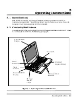
The notebook contains an alternate action power switch located on the left side of the
notebook as shown in Figure 3-1. The first time you press the power switch, power is
turned on to the notebook. The next time you press the power switch, power is turned
off.
3.2.2 Notebook LEDs
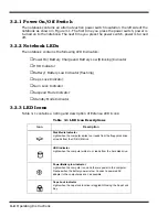
The notebook contains the following LED Indicators:
♦
Power On/Battery Charge and Battery Low (Blinking) Indicator
♦
HDD Indicator
♦
Battery/ Battery Low Indicator (flashing)
♦
Caps Lock Indicator
♦
Num Lock Indicator
♦
Suspend Mode Indicator
♦
Standby Mode Indicator
3.2.3 LED Icons
Table 3-1 contains a listing and description of Extensa LED Icons:
Table 3-1 LED Icon Descriptions
Icon
Description
Disk Media Indicator
Lights when the computer writes to or reads from the floppy disk drive,
or reads from the CD-ROM drive.
HDD Indicator
Lights when the computer writes to or reads from the hard disk drive.
Power/Battery-low Indicator
Lights when the computer is on and there is power to the computer.
Flashes when the battery power is low. Connect a powered AC
adapter to the computer as soon as possible.
Caps Lock Indicator
Lights when the caps lock function is toggled ON using the Caps Lock
Key.
Summary of Contents for Extensa 660 Series
Page 1: ...Maintenance Manual ExtensaTM 660 Series Notebook Computers 9813214 0001 Rev A February 1997 ...
Page 42: ......
Page 60: ......
Page 94: ......
Page 122: ......
Page 124: ...A 2 Schematic Diagrams Figure A 1 Motherboard PWB Logic Diagrams Sheet 1 of 23 ...
Page 125: ...Schematic Diagrams A 3 Figure A 2 Motherboard PWB Logic Diagrams Sheet 2 of 23 ...
Page 126: ...A 4 Schematic Diagrams Figure A 1 Motherboard PWB Logic Diagrams Sheet 3 of 23 ...
Page 127: ...Schematic Diagrams A 5 Figure A 1 Motherboard PWB Logic Diagrams Sheet 4 of 23 ...
Page 128: ...A 6 Schematic Diagrams Figure A 1 Motherboard PWB Logic Diagrams Sheet 5 of 23 ...
Page 129: ...Schematic Diagrams A 7 Figure A 1 Motherboard PWB Logic Diagrams Sheet 6 of 23 ...
Page 130: ...A 8 Schematic Diagrams Figure A 1 Motherboard PWB Logic Diagrams Sheet 7 of 23 ...
Page 131: ...Schematic Diagrams A 9 Figure A 1 Motherboard PWB Logic Diagrams Sheet 8 of 23 ...
Page 132: ...A 10 Schematic Diagrams Figure A 1 Motherboard PWB Logic Diagrams Sheet 9 of 23 ...
Page 133: ...Schematic Diagrams A 11 Figure A 1 Motherboard PWB Logic Diagrams Sheet 10 of 23 ...
Page 134: ...A 12 Schematic Diagrams Figure A 1 Motherboard PWB Logic Diagrams Sheet 11 of 23 ...
Page 135: ...Schematic Diagrams A 13 Figure A 1 Motherboard PWB Logic Diagrams Sheet 12 of 23 ...
Page 136: ...A 14 Schematic Diagrams Figure A 1 Motherboard PWB Logic Diagrams Sheet 13 of 23 ...
Page 137: ...Schematic Diagrams A 15 Figure A 1 Motherboard PWB Logic Diagrams Sheet 14 of 23 ...
Page 138: ...A 16 Schematic Diagrams Figure A 1 Motherboard PWB Logic Diagrams Sheet 15 of 23 ...
Page 139: ...Schematic Diagrams A 17 Figure A 1 Motherboard PWB Logic Diagrams Sheet 16 of 23 ...
Page 140: ...A 18 Schematic Diagrams Figure A 1 Motherboard PWB Logic Diagrams Sheet 17 of 23 ...
Page 141: ...Schematic Diagrams A 19 Figure A 1 Motherboard PWB Logic Diagrams Sheet 18 of 23 ...
Page 142: ...A 20 Schematic Diagrams Figure A 1 Motherboard PWB Logic Diagrams Sheet 19 of 23 ...
Page 143: ...Schematic Diagrams A 21 Figure A 1 Motherboard PWB Logic Diagrams Sheet 20 of 23 ...
Page 144: ...A 22 Schematic Diagrams Figure A 1 Motherboard PWB Logic Diagrams Sheet 21 of 23 ...
Page 145: ...Schematic Diagrams A 23 Figure A 1 Motherboard PWB Logic Diagrams Sheet 22 of 23 ...
Page 146: ...A 24 Schematic Diagrams Figure A 1 Motherboard PWB Logic Diagrams Sheet 23 of 23 ...
Page 147: ......


