3-4
Operating Instructions
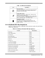
3.2.4.1
Windows 95 Special Keys
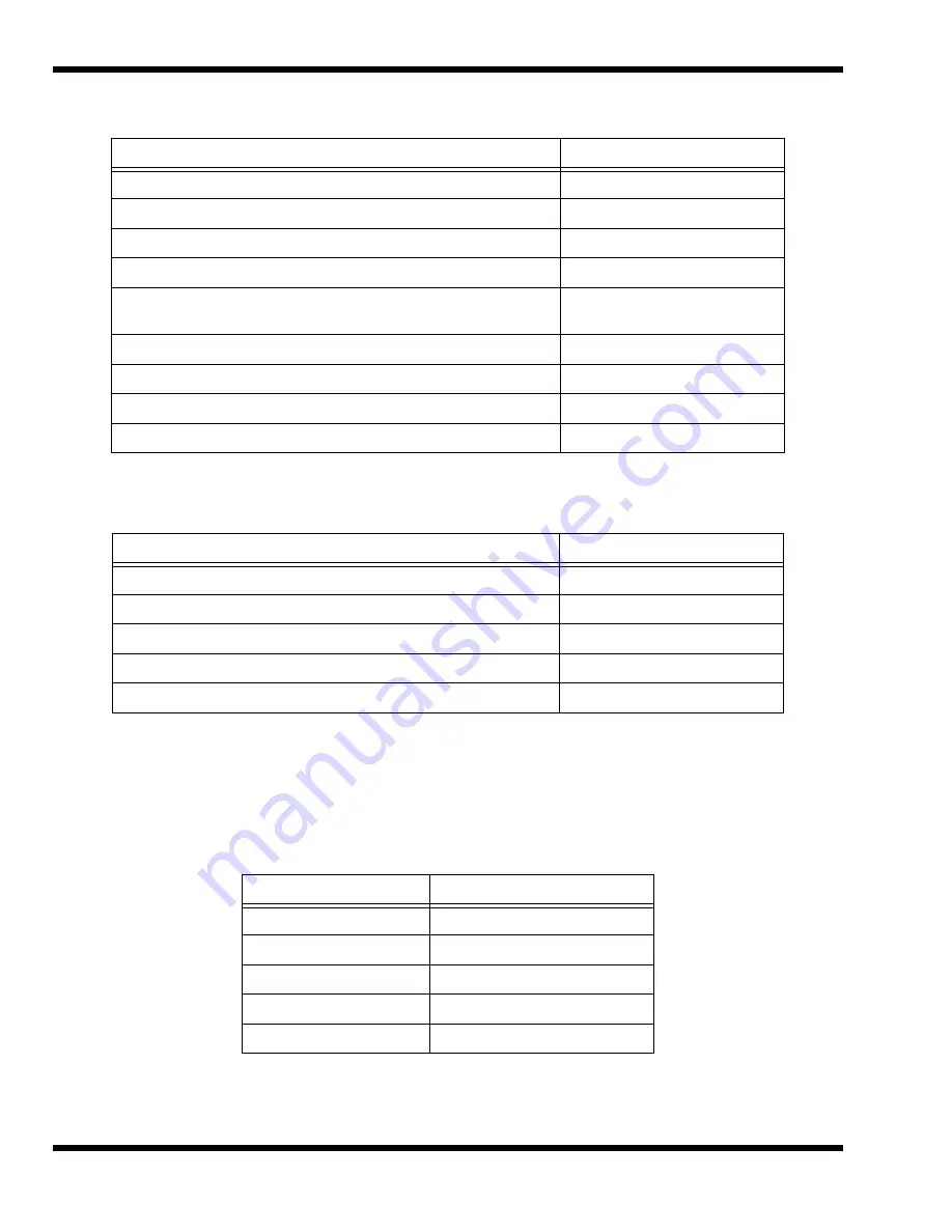
Pressing the Windows Logo Key
acts as the Start button. Pressing this key in
combination with other keys performs special functions. Table 3-4 contains several
examples of using the Windows 95 special keys.
Pressing the Application Key displays the context menu for an application. This is the
same as clicking the secondary (right) mouse button.
Toggle speaker output on/off
Fn+End
Stop a command or application
Ctrl+Pause
Resume a command or application
Press any key
Send the contents of the screen to the printer
Shift+PrtSc
Sets the notebook to echo keystrokes to the printer; prints a line when
you press Enter; continues until you press Ctrl+P
Ctrl+P
Enable/disable the internal keypad
Fn+T
Warm boot
Ctrl+Alt+Del
Start
Windows logo key
Display the application’s context menu
Application key
Table 3-3 Hot Keys Available on Attached External keyboard
Function
Key Sequence
System Setup
Ctrl+Alt+F1
0V Suspend
Ctrl+Alt+F2
5V Suspend
Ctrl+Alt+F3
LCD/CRT Toggle
Ctrl+Alt+F12
Speaker Toggle
Ctrl+Alt+S
Table 3-4 Windows 95 Special Keys
Hot Key
Function
Windows Logo Key+Tab
Activates next Taskbar button
Windows Logo Key+E
Explore my Computer
Windows Logo Key+F
Find Document
Windows Logo Key+M
Minimize All
Windows Logo Key+R
Display Run dialog box
Table 3-2 Summary of Notebook Hot Key Sequences
Function
Key Sequence
Summary of Contents for Extensa 660 Series
Page 1: ...Maintenance Manual ExtensaTM 660 Series Notebook Computers 9813214 0001 Rev A February 1997 ...
Page 42: ......
Page 60: ......
Page 94: ......
Page 122: ......
Page 124: ...A 2 Schematic Diagrams Figure A 1 Motherboard PWB Logic Diagrams Sheet 1 of 23 ...
Page 125: ...Schematic Diagrams A 3 Figure A 2 Motherboard PWB Logic Diagrams Sheet 2 of 23 ...
Page 126: ...A 4 Schematic Diagrams Figure A 1 Motherboard PWB Logic Diagrams Sheet 3 of 23 ...
Page 127: ...Schematic Diagrams A 5 Figure A 1 Motherboard PWB Logic Diagrams Sheet 4 of 23 ...
Page 128: ...A 6 Schematic Diagrams Figure A 1 Motherboard PWB Logic Diagrams Sheet 5 of 23 ...
Page 129: ...Schematic Diagrams A 7 Figure A 1 Motherboard PWB Logic Diagrams Sheet 6 of 23 ...
Page 130: ...A 8 Schematic Diagrams Figure A 1 Motherboard PWB Logic Diagrams Sheet 7 of 23 ...
Page 131: ...Schematic Diagrams A 9 Figure A 1 Motherboard PWB Logic Diagrams Sheet 8 of 23 ...
Page 132: ...A 10 Schematic Diagrams Figure A 1 Motherboard PWB Logic Diagrams Sheet 9 of 23 ...
Page 133: ...Schematic Diagrams A 11 Figure A 1 Motherboard PWB Logic Diagrams Sheet 10 of 23 ...
Page 134: ...A 12 Schematic Diagrams Figure A 1 Motherboard PWB Logic Diagrams Sheet 11 of 23 ...
Page 135: ...Schematic Diagrams A 13 Figure A 1 Motherboard PWB Logic Diagrams Sheet 12 of 23 ...
Page 136: ...A 14 Schematic Diagrams Figure A 1 Motherboard PWB Logic Diagrams Sheet 13 of 23 ...
Page 137: ...Schematic Diagrams A 15 Figure A 1 Motherboard PWB Logic Diagrams Sheet 14 of 23 ...
Page 138: ...A 16 Schematic Diagrams Figure A 1 Motherboard PWB Logic Diagrams Sheet 15 of 23 ...
Page 139: ...Schematic Diagrams A 17 Figure A 1 Motherboard PWB Logic Diagrams Sheet 16 of 23 ...
Page 140: ...A 18 Schematic Diagrams Figure A 1 Motherboard PWB Logic Diagrams Sheet 17 of 23 ...
Page 141: ...Schematic Diagrams A 19 Figure A 1 Motherboard PWB Logic Diagrams Sheet 18 of 23 ...
Page 142: ...A 20 Schematic Diagrams Figure A 1 Motherboard PWB Logic Diagrams Sheet 19 of 23 ...
Page 143: ...Schematic Diagrams A 21 Figure A 1 Motherboard PWB Logic Diagrams Sheet 20 of 23 ...
Page 144: ...A 22 Schematic Diagrams Figure A 1 Motherboard PWB Logic Diagrams Sheet 21 of 23 ...
Page 145: ...Schematic Diagrams A 23 Figure A 1 Motherboard PWB Logic Diagrams Sheet 22 of 23 ...
Page 146: ...A 24 Schematic Diagrams Figure A 1 Motherboard PWB Logic Diagrams Sheet 23 of 23 ...
Page 147: ......


