Operating Instructions
3-9
3.7.1 Lowering Inactivity Timeouts
Inactivity timeouts turn off devices in the computer when you are not using them.
Lowering the inactivity timeouts shortens the period of time the computer waits before
turning off the device.
3.7.2 Suspending Operation While Idle
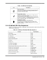
Although the computer goes into Suspend mode automatically after a defined period of
inactivity, you can reduce energy consumption even further by pressing either
Fn+F3
(
Suspend
) or
Fn+F4
(
Standby
) as soon as you no longer need the computer to be active.
♦
Pressing
Fn+F4
(
Standby
) turns off the screen.
♦
Pressing
Fn+F3
(
Suspend
) turns off the screen, stops the hard disk, and
reduces energy usage to the lowest level possible without turning off the
computer.
♦
Pressing the
Shift
key resumes activity after the notebook has been in either
the Suspend or Standby modes.
3.7.3 Responding to a Low Battery Condition
When you are operating the computer on battery power and the charge remaining is
down to between 10% and 20%, the battery-low indicator blinks and an audible alarm
sounds. When this happens you should take the following actions to conserve battery
power and reduce the possibility of data loss.
♦
Saving files — Save all open files frequently while the computer is in a low-
battery condition.
♦
Turning off the alarm — Turn off the audible alarm by pressing
Fn+End
(
Mute
).
♦
Reducing screen brightness — Reduce screen brightness by pressing
Fn
+
↓
.
♦
Connecting the AC adapter — If you have access to AC power, connect the
computer to the AC adapter. You can do this without turning off the computer.
♦
Suspending operations — Press
Fn+F3
or
Fn+F4
to put the computer into
Suspend or Standby mode whenever you are not actively using the computer.
Press the
Shift
key to bring the computer out of Suspend or Standby mode.
Summary of Contents for Extensa 660 Series
Page 1: ...Maintenance Manual ExtensaTM 660 Series Notebook Computers 9813214 0001 Rev A February 1997 ...
Page 42: ......
Page 60: ......
Page 94: ......
Page 122: ......
Page 124: ...A 2 Schematic Diagrams Figure A 1 Motherboard PWB Logic Diagrams Sheet 1 of 23 ...
Page 125: ...Schematic Diagrams A 3 Figure A 2 Motherboard PWB Logic Diagrams Sheet 2 of 23 ...
Page 126: ...A 4 Schematic Diagrams Figure A 1 Motherboard PWB Logic Diagrams Sheet 3 of 23 ...
Page 127: ...Schematic Diagrams A 5 Figure A 1 Motherboard PWB Logic Diagrams Sheet 4 of 23 ...
Page 128: ...A 6 Schematic Diagrams Figure A 1 Motherboard PWB Logic Diagrams Sheet 5 of 23 ...
Page 129: ...Schematic Diagrams A 7 Figure A 1 Motherboard PWB Logic Diagrams Sheet 6 of 23 ...
Page 130: ...A 8 Schematic Diagrams Figure A 1 Motherboard PWB Logic Diagrams Sheet 7 of 23 ...
Page 131: ...Schematic Diagrams A 9 Figure A 1 Motherboard PWB Logic Diagrams Sheet 8 of 23 ...
Page 132: ...A 10 Schematic Diagrams Figure A 1 Motherboard PWB Logic Diagrams Sheet 9 of 23 ...
Page 133: ...Schematic Diagrams A 11 Figure A 1 Motherboard PWB Logic Diagrams Sheet 10 of 23 ...
Page 134: ...A 12 Schematic Diagrams Figure A 1 Motherboard PWB Logic Diagrams Sheet 11 of 23 ...
Page 135: ...Schematic Diagrams A 13 Figure A 1 Motherboard PWB Logic Diagrams Sheet 12 of 23 ...
Page 136: ...A 14 Schematic Diagrams Figure A 1 Motherboard PWB Logic Diagrams Sheet 13 of 23 ...
Page 137: ...Schematic Diagrams A 15 Figure A 1 Motherboard PWB Logic Diagrams Sheet 14 of 23 ...
Page 138: ...A 16 Schematic Diagrams Figure A 1 Motherboard PWB Logic Diagrams Sheet 15 of 23 ...
Page 139: ...Schematic Diagrams A 17 Figure A 1 Motherboard PWB Logic Diagrams Sheet 16 of 23 ...
Page 140: ...A 18 Schematic Diagrams Figure A 1 Motherboard PWB Logic Diagrams Sheet 17 of 23 ...
Page 141: ...Schematic Diagrams A 19 Figure A 1 Motherboard PWB Logic Diagrams Sheet 18 of 23 ...
Page 142: ...A 20 Schematic Diagrams Figure A 1 Motherboard PWB Logic Diagrams Sheet 19 of 23 ...
Page 143: ...Schematic Diagrams A 21 Figure A 1 Motherboard PWB Logic Diagrams Sheet 20 of 23 ...
Page 144: ...A 22 Schematic Diagrams Figure A 1 Motherboard PWB Logic Diagrams Sheet 21 of 23 ...
Page 145: ...Schematic Diagrams A 23 Figure A 1 Motherboard PWB Logic Diagrams Sheet 22 of 23 ...
Page 146: ...A 24 Schematic Diagrams Figure A 1 Motherboard PWB Logic Diagrams Sheet 23 of 23 ...
Page 147: ......


