


Specification Summary
www.ti.com
4
Specification Summary
•
Space saving footprint
•
Wide ambient temperature range: -40 ºC to 65 ºC
•
Input voltage range: 8V to 14V
•
Adjustable output voltage: 1.2V to 3.3V
•
No minimum load requirement
•
Remote ON/OFF
•
Power good signal
•
Fixed switching frequency: 300 kHz
•
Switching frequency synchronize range 250 kHz to 1 MHz
•
Current Limit Protection
•
Master power supply start-up tracking function
•
Start-up with a pre-biased output load
•
Adjustable soft-start
•
Small size 2.19 in. x 1.03 in. x 0.41 in. (56 mm x 26.2 mm x 10.3 mm)
5
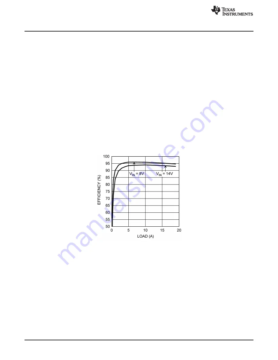
Performance Characteristics
Efficiency
Figure 2. Efficiency vs. Load Current
V
OUT
= 3.3V, f
SW
= 300 kHz
2
AN-1573 LM2745-19A Demonstration Board
SNVA213A – May 2007 – Revised May 2013
Submit Documentation Feedback
Copyright © 2007–2013, Texas Instruments Incorporated


