Setup
2 LM75AEB
User’s Guide
July 2012
2.1. Input/Output Connector Description
JP2 – Output
is a header that allows user to probe the LM75AIM’s VDD, GND, A0, A1, A2, OS#, and I
2
C
pins.
JP4 – VDD
is the power input terminal for the LM75AIM. The jumper terminal provides power to LM75AIM
VDD pin.
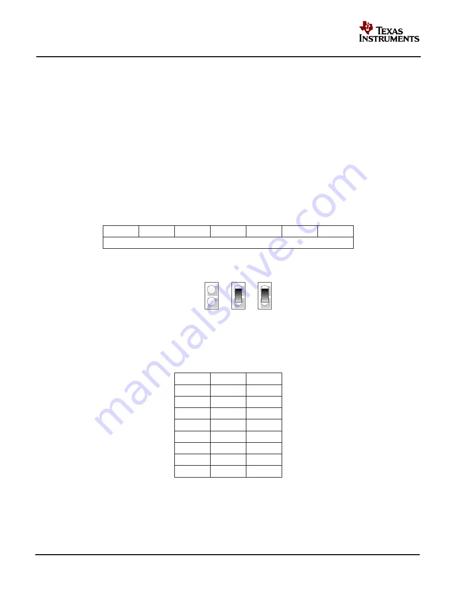
JP5 – A0
is bit 0 of the three least significant bits of the I2C slave address. At default, this jumper is pulling
high, and jumping the two terminals allows setting A0 low.
JP6 – A1
is bit 1 of the three least significant bits of the I2C slave address. At default, this jumper is pulling
high, and jumping the two terminals allows setting A1 low.
JP7 – A2
is bit 2 of the three least significant bits of the I2C slave address. At default, this jumper is pulling
high, and jumping the two terminals allows setting A2 low.
1
0
0
1
A2
A1
A0
MSB
LSB
Figure 1: 7-bit Slave Address
JP5
JP6
JP7
A0
A1
A2
Figure 2: Three Significant Bits
A2
A1
A0
0
0
0
0
0
1
0
1
0
0
1
1
1
0
0
1
0
1
1
1
0
1
1
1
Table 1: I2C Address User Setting Input


