Table B-3. Output Termination Configuration (continued)
OUTPUT FORMAT
COUPLING
COMPONENT
VALUE
HCSL
AC
R25, R28
0 Ω
R26, R29
50 Ω
C24, C25
0.01 µF
R27, R30, R31
DNP
DC
R25, R28, C24, C25
0 Ω
R26, R29
50 Ω
R27, R30, R31
DNP
(1)
50-Ω to V
CC
– 2-V termination is required on receiver.
(2)
100-Ω differential termination (R31) is provided onboard. Removing this termination is possible if the differential termination is available
on the receiver.
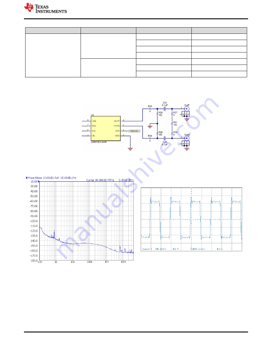
Figure B-1. Output Termination Schematic
B.3 Typical Output Characteristics
Figure B-2. Default Output Phase Nosie
Figure B-3. Default Output Waveform
B.4 Firmware Update
Usually when the Reference PRO board is used at the first time, TICS Pro will request for a firmware update.
Simply follow the pop-up instructions to complete the update. This is necessary to ensure that the USB
connection between the PC and the Reference PRO board is properly setup, otherwise the programming to
LMX2571EPEVM will not be successful.
1. When you see this message, click the
OK
button.
Reference PRO
SNAU182 – MARCH 2021
LMX2571EPEVM Evaluation Instructions
17
Copyright © 2021 Texas Instruments Incorporated


