PCB Layout
www.ti.com
22
SNVU578A – October 2017 – Revised March 2018
Submit Documentation Feedback
Copyright © 2017–2018, Texas Instruments Incorporated
User's Guide for the LMZM23601 and LMZM23600 Evaluation Boards
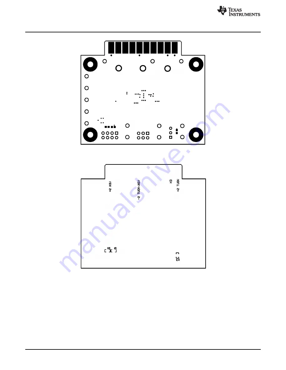
Figure 42. Fixed Output Board Layout - Bottom Soldermask
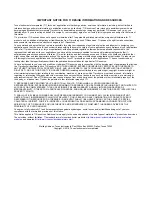
Figure 43. Fixed Output Board Layout - Bottom Overlay


