2 Hardware and Software Preparation
This following chapters describe how to set up the LP5860EVM and GUI properly. Items from the following list
are required to begin evaluating the LP5860:
• Computer
• LP5860EVM kit hardware
• LP586x GUI software
2.1 Hardware Setup
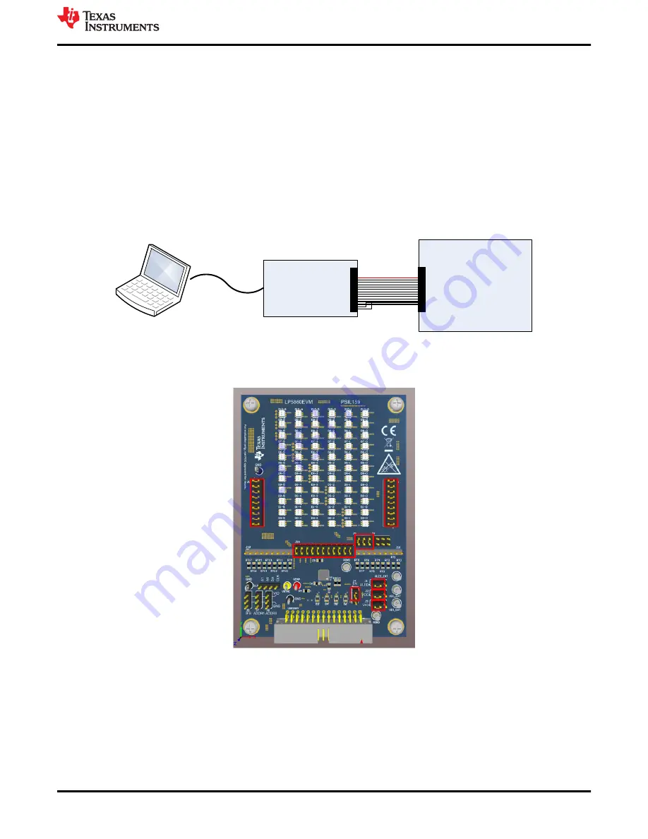
In the default jumper setting, the board can be evaluated by USB power directly and does not need an external
power supply. Setup connection is demonstrated in
. The setup procedure follows:
1. Connect the USB2ANY with the LP5860EVM using the 30-pin ribbon cable
2. Plug the USB cable into the USB port on the computer
USB2ANY
LP5860EVM
USB cable
Ribbon Cable
Figure 2-1. Hardware Connection
shows the default jumper settings.
Figure 2-2. Default Jumper Setting
If maximum current is set above 20 mA, an external VLED supply is recommended during evaluation, since the
USB can only provide around 400-mA current. The setup procedure follows:
1. Connect the USB2ANY to the LP5860EVM using the 30-pin ribbon cable
2. Connect a 5-V external power supply to the VLED_EXT terminal (see
) and connect the switching
jumper (J1) to another side
3. Plug the USB cable into the USB port on the computer
Hardware and Software Preparation
SNVU762 – MAY 2021
LP5860 Evaluation Module
3
Copyright © 2021 Texas Instruments Incorporated


