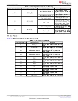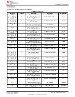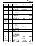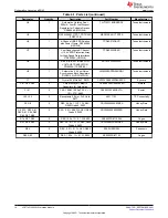
Table 3-2. Configuration Jumpers (continued)
Jumper/Connector Number
Jumper/Connector Name
Configuration
Description
J17
VMON1_SEL
Pins 1 and 2 (Default: open)
VMON1 reference voltage
generated from voltage divider on
VIO supply
Pins 2 and 3 (Default: open)
VMON1 voltage taken from
BUCK1 (1.0 V) output
J18
nERR_GPO2
Pins 1 and 2 (Default)
Connects PMIC nERR_GPO
signal to MCU port directly
Pins 2 and 3
Connects PMIC nERR_GPO2
signal to MCU port through level
shifter (series resistors must be
mounted if this option is used)
J19
nRSTOUT
Pins 1 and 2 (Default)
Connects PMIC nRSTOUT signal
to MCU port directly
Pins 2 and 3
Connects PMIC nRSTOUT signal
to MCU port through level shifter
(series resistors must be mounted
if this option is used)
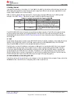
3.1 Test Points
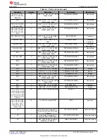
lists all the available connectors on the EVM.
Table 3-3. Test Points on the EVM
Connector Number
Connector Name
Description
J2
USB_5V_S
Test point to measure 5 V supply from USB
cable
J12
VOUT_VLDO
Test point to measure VOUT_VLDO output
J22
Load Module Connector
Connector placeholder for
PMICLOADBOARDEVM for doing load
transient testing
J23
Load Module Connector
Connector placeholder for
PMICLOADBOARDEVM for doing load
transient testing
J24
FB_B1
Test point to measure the BUCK1 feedback
signal
J25
FB_B2
Test point to measure the BUCK2 feedback
signal
J26
FB_B3
Test point to measure the BUCK3 feedback
signal
J28
J28
SMA connector for BUCK3 noise
measurement
J30
J30
SMA connector for BUCK2 noise
measurement
J32
J32
SMA connector for BUCK1 noise
measurement
J36
VBAT_PIN_S
Test point to measure the VBAT input supply
Jumpers and connectors
6
LP877451Q1EVM Evaluation Module
Copyright © 2021 Texas Instruments Incorporated


