background image

Device

Package

Type

Package

Drawing

Pins

SPQ

Reel

Diameter

(mm)

Reel

Width

W1 (mm)

A0

(mm)

B0

(mm)

K0

(mm)

P1

(mm)

W

(mm)

Pin1

Quadrant

OR

MSP430FG4618IZQWT

BGA MI 

CROSTA

R JUNI 

OR

ZQW

113

250

330.0

16.4

7.3

7.3

1.5

12.0

16.0

Q1

MSP430FG4619IPZR

LQFP

PZ

100

1000

330.0

24.4

17.4

17.4

2.0

20.0

24.0

Q2

MSP430FG4619IZQWR

BGA MI 

CROSTA

R JUNI 

OR

ZQW

113

2500

330.0

16.4

7.3

7.3

1.5

12.0

16.0

Q1

MSP430FG4619IZQWT

BGA MI 

CROSTA

R JUNI 

OR

ZQW

113

250

330.0

16.4

7.3

7.3

1.5

12.0

16.0

Q1

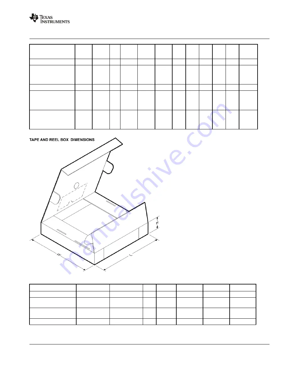
*All dimensions are nominal

Device

Package Type

Package Drawing

Pins

SPQ

Length (mm)

Width (mm)

Height (mm)

MSP430FG4616IPZR

LQFP

PZ

100

1000

367.0

367.0

45.0

MSP430FG4616IZQWR

BGA MICROSTAR

JUNIOR

ZQW

113

2500

336.6

336.6

28.6

MSP430FG4616IZQWT

BGA MICROSTAR

JUNIOR

ZQW

113

250

336.6

336.6

28.6

MSP430FG4617IPZR

LQFP

PZ

100

1000

367.0

367.0

45.0

PACKAGE MATERIALS INFORMATION

www.ti.com

13-Sep-2013

Pack Materials-Page 2

Summary of Contents for MSP430CG4616IPZ

Page 1: ...different sets of peripherals targeted for various applications The architecture combined with five low power modes is optimized to achieve extended battery life in portable measurement applications...

Page 2: ...he most current package and ordering information see the Package Option Addendum at the end of this document or see the TI web site at www ti com Package drawings thermal data and symbolization are av...

Page 3: ...P1 0 TA0 TDI TCLK TDO TDI P8 4 S21 SS1 DV P6 2 A2 OA0I1 P1 2 TA1 P8 1 S24 P4 6 UCA0TXD S35 DVCC1 P6 3 A3 OA1O P6 4 A4 OA1I0 P6 5 A5 OA2O P6 6 A6 DAC0 OA2I0 P6 7 A7 DAC1 SVSIN VREF XIN XOUT VeREF DAC0...

Page 4: ...08I APRIL 2006 REVISED MARCH 2011 4 POST OFFICE BOX 655303 DALLAS TEXAS 75265 pin designation MSP430xG461xIZQW top view A B C D E F G H J K L M 1 2 3 4 5 6 7 8 9 10 11 12 NOTE For terminal assignments...

Page 5: ...Real Time Clock JTAG Interface LCD_A 160 Segments 1 2 3 4 Mux Ports P1 P2 2x8 I O Interrupt capability USCI_A0 UART IrDA SPI USCI_B0 SPI I2C Comparator _A Flash FG ROM CG 120kB 116kB 92kB 92kB Hardwar...

Page 6: ...2I1 see Note 1 14 E5 I O General purpose digital I O LCD segment output 2 analog input a14 12 bit ADC OA2 input multiplexer on terminal and terminal P10 6 S3 A15 see Note 1 15 G1 I O General purpose d...

Page 7: ...output 36 P4 4 SOMI1 S37 49 H7 I O General purpose digital I O slave out master in of USART1 SPI mode LCD segment output 37 P4 3 SIMO1 S38 50 M10 I O General purpose digital I O slave in master out of...

Page 8: ...0 I O General purpose digital I O Comparator_A input P1 6 CA0 81 A9 I O General purpose digital I O Comparator_A input P1 5 TACLK ACLK 82 B9 I O General purpose digital I O Timer_A clock signal TACLK...

Page 9: ...plies SVS brownout oscillator comparator_A port 1 DVSS1 see Note 1 99 B3 Digital supply voltage negative terminal AVCC 100 A2 Analog supply voltage positive terminal Supplies SVS brownout oscillator c...

Page 10: ...ddressing modes for destination operand The CPU is integrated with 16 registers that provide reduced instruction execution time The register to register operation execution time is one cycle of the CP...

Page 11: ...itional e g JNE Jump on equal bit 0 Table 2 Address Mode Descriptions ADDRESS MODE S D SYNTAX EXAMPLE OPERATION Register F F MOV Rs Rd MOV R10 R11 R10 R11 Indexed F F MOV X Rn Y Rm MOV 2 R5 6 R6 M 2 R...

Page 12: ...locks are active D Low power mode 0 LPM0 CPU is disabled ACLK and SMCLK remain active MCLK is disabled FLL loop control remains active D Low power mode 1 LPM1 CPU is disabled FLL loop control is disab...

Page 13: ...t UCA0TXIFG UCB0TXIFG see Note 1 Maskable 0FFF0h 24 ADC12 ADC12IFG see Notes 1 and 2 Maskable 0FFEEh 23 Timer_A3 TACCR0 CCIFG0 see Note 2 Maskable 0FFECh 22 Timer_A3 TACCR1 CCIFG1 and TACCR2 CCIFG2 TA...

Page 14: ...if watchdog mode is selected Active if watchdog timer is configured as a general purpose timer OFIE Oscillator fault interrupt enable NMIIE Nonmaskable interrupt enable ACCVIE Flash access violation...

Page 15: ...B0TXIFG UCB0RXIFG rw 0 rw 0 UCA0RXIFG USCI_A0 receive interrupt flag UCA0TXIFG USCI_A0 transmit interrupt flag UCB0RXIFG USCI_B0 receive interrupt flag UCB0TXIFG USCI_B0 transmit interrupt flag URXIFG...

Page 16: ...B 09FFh 0200h Peripherals 16 bit 8 bit 8 bit SFR 01FFh 0100h 0FFh 010h 0Fh 00h 01FFh 0100h 0FFh 010h 0Fh 00h 01FFh 0100h 0FFh 010h 0Fh 00h 01FFh 0100h 0FFh 010h 0Fh 00h MSP430CG4616 MSP430CG4617 MSP43...

Page 17: ...invalid password is supplied 0AA55h BSL disabled any other value BSL enabled BSL FUNCTION PZ ZQW PACKAGE PINS Data Transmit 87 A7 P1 0 Data Receive 86 E7 P1 1 flash memory The flash memory can be pro...

Page 18: ...l or a high frequency crystal D Main clock MCLK the system clock used by the CPU D Sub Main clock SMCLK the subsystem clock used by the peripheral modules D ACLK n the buffered output of ACLK ACLK 2 A...

Page 19: ...s at selected time intervals universal serial communication interface USCI The USCI modules are used for serial data communication The USCI module supports synchronous communication protocols like SPI...

Page 20: ...from each of the capture compare registers Timer_A3 Signal Connections Input Pin Number Device Input Module Input Module Module Output Output Pin Number PZ ZQW Device Input Signal Module Input Name M...

Page 21: ...put Name Module Block Module Output Signal PZ ZQW 83 B8 P1 4 TBCLK TBCLK ACLK ACLK Timer NA SMCLK SMCLK Timer NA 83 B8 P1 4 TBCLK INCLK 78 D8 P2 1 TB0 CCI0A 78 D8 P2 1 78 D8 P2 1 TB0 CCI0B CCR0 TB0 AD...

Page 22: ...present they may be grouped together for synchronous operation OA The MSP430xG461x has three configurable low current general purpose operational amplifiers Each OA input and output terminal is softwa...

Page 23: ...ompare control 2 TBCCTL2 0186h Capture compare control 1 TBCCTL1 0184h Capture compare control 0 TBCCTL0 0182h Timer_B control TBCTL 0180h Timer_B interrupt vector TBIV 011Eh Timer_A3 Capture compare...

Page 24: ...hannel 0 control DMA0CTL 01D0h DMA channel 0 source address DMA0SA 01D2h DMA channel 0 destination address DMA0DA 01D6h DMA channel 0 transfer size DMA0SZ 01DAh DMA Channel 1 DMA channel 1 control DMA...

Page 25: ...rsion memory 6 ADC12MEM6 014Ch Conversion memory 5 ADC12MEM5 014Ah Conversion memory 4 ADC12MEM4 0148h Conversion memory 3 ADC12MEM3 0146h Conversion memory 2 ADC12MEM2 0144h Conversion memory 1 ADC12...

Page 26: ...C memory control register 15 ADC12MCTL15 08Fh Memory control registers require byte ADC memory control register 14 ADC12MCTL14 08Eh registers require byte access ADC memory control register 13 ADC12MC...

Page 27: ...ve Control UCAIRRCTL 05Fh USCI IrDA Transmit Control UCAIRTCTL 05Eh USCI LIN Control UCAABCTL 05Dh Comparator_A Comparator_A port disable CAPD 05Bh p _ Comparator_A control 2 CACTL2 05Ah Comparator_A...

Page 28: ...n P6SEL 037h Port P6 direction P6DIR 036h Port P6 output P6OUT 035h Port P6 input P6IN 034h Port P5 Port P5 selection P5SEL 033h Port P5 direction P5DIR 032h Port P5 output P5OUT 031h Port P5 input P5...

Page 29: ...655303 DALLAS TEXAS 75265 peripheral file map continued PERIPHERALS WITH BYTE ACCESS CONTINUED Special functions SFR module enable 2 ME2 005h p SFR module enable 1 ME1 004h SFR interrupt flag 2 IFG2...

Page 30: ...ing program execution SVS enabled and PORON 1 see Note 1 and Note 2 VCC AVCC DVCC1 2 VCC MSP430xG461x 2 3 6 V Supply voltage see Note 1 VSS AVSS DVSS1 2 VSS 0 0 V Operating free air temperature range...

Page 31: ...40 C 1 9 5 0 A static mode fLCD f ACLK 32 see Note 2 and Note 3 and Note 4 TA 25 C V 3 V 1 9 5 0 see Note 2 and Note 3 and Note 4 TA 60 C VCC 3 V 2 5 7 5 TA 85 C 7 5 18 0 Low power mode LPM3 TA 40 C...

Page 32: ...t int External interrupt timing Port P1 P2 P1 x to P2 x external trigger signal for the interrupt flag see Note 1 3 V 50 ns t Timer_A Timer_B capture TA0 TA1 TA2 2 2 V 62 ns t cap Timer_A Timer_B capt...

Page 33: ...S 0 6 NOTES 1 The maximum total current IOH max and IOL max for all outputs combined should not exceed 12 mA to satisfy the maximum specified voltage drop 2 The maximum total current IOH max and IOL m...

Page 34: ...Current mA Figure 3 VOL Low Level Output Voltage V 0 0 10 0 20 0 30 0 40 0 50 0 0 0 0 5 1 0 1 5 2 0 2 5 3 0 3 5 VCC 3 V P2 0 TYPICAL LOW LEVEL OUTPUT CURRENT vs LOW LEVEL OUTPUT VOLTAGE TA 25 C TA 85...

Page 35: ...wake up LPM3 PARAMETER TEST CONDITIONS MIN TYP MAX UNIT f 1 MHz 6 td LPM3 Delay time f 2 MHz VCC 2 2 V 3 V 6 s td LPM3 Delay time f 3 MHz VCC 2 2 V 3 V 6 s RAM PARAMETER TEST CONDITIONS MIN TYP MAX U...

Page 36: ...2 78 VLCDx 0101 2 84 VLCDx 0110 2 90 V LCD voltage see Note 3 VLCDx 0111 2 96 V VLCD LCD voltage see Note 3 VLCDx 1000 3 02 V VLCDx 1001 3 08 VLCDx 1010 3 14 VLCDx 1011 3 20 VLCDx 1100 3 26 VLCDx 110...

Page 37: ...at P1 6 CA0 and P1 7 CA1 VCC 2 2 V 390 480 540 mV V RefVT No load at P1 6 CA0 and P1 7 CA1 TA 85 C VCC 3 V 400 490 550 mV VIC Common mode input voltage range CAON 1 VCC 2 2 V 3 V 0 VCC 1 V Vp VS Offs...

Page 38: ...ference Voltage mV Typical REFERENCE VOLTAGE vs FREE AIR TEMPERATURE Figure 7 V RefVT vs Temperature TA Free Air Temperature C 400 450 500 550 600 650 45 25 5 15 35 55 75 95 VCC 2 2 V Typical REFERENC...

Page 39: ...current consumption of the brownout module is already included in the ICC current consumption data 2 The voltage level V B_IT Vhys B_IT is 1 89V 3 During power up the CPU begins code execution followi...

Page 40: ..._IT VCC dt 3 V s see Figure 13 VLD 2 14 V SVS_IT x 0 001 V SVS_IT x 0 016 Vhys SVS_IT VCC dt 3 V s see Figure 13 external voltage applied on A7 VLD 15 4 4 20 mV VLD 1 1 8 1 9 2 05 VLD 2 1 94 2 1 2 23...

Page 41: ...Vhys SVS_IT 0 1 td BOR Brownout 0 1 td SVSon td BOR 0 1 Set POR Brown Out Region SVS Circuit is Active From VLD to VCC V B_IT SVSOut Vhys B_IT Figure 13 SVS Reset SVSR vs Supply Voltage 0 0 5 1 1 5 2...

Page 42: ...FN 2 x DCOPLUS 1 2 2 V 9 15 5 25 MHz f DCO 27 FN_8 FN_4 0 FN_3 1 FN_2 x DCOPLUS 1 3 V 10 3 17 9 28 5 MHz f FN 8 0 FN 4 1 FN 3 FN 2 x DCOPLUS 1 2 2 V 1 8 2 8 4 2 MHz f DCO 2 FN_8 0 FN_4 1 FN_3 FN_2 x D...

Page 43: ...DCO Tap S n Stepsize Ratio between DCO Taps Min Max 1 07 1 06 Figure 16 DCO Tap Step Size DCO Frequency Adjusted by Bits 29 to 25 in SCFI1 N DCO FN_2 0 FN_3 0 FN_4 0 FN_8 0 FN_2 1 FN_3 0 FN_4 0 FN_8 0...

Page 44: ...s short as possible Design a good ground plane around the oscillator pins Prevent crosstalk from other clock or data lines into oscillator pins XIN and XOUT Avoid running PCB traces underneath or adja...

Page 45: ...DITIONS VCC MIN TYP MAX UNIT fUSCI USCI input clock frequency SMCLK ACLK Duty Cycle 50 10 fSYSTEM MHz t SOMI input data setup time 2 2 V 110 ns tSU MI SOMI input data setup time 3 V 75 ns t SOMI input...

Page 46: ...stics over recommended ranges of supply voltage and operating free air temperature unless otherwise noted continued UCLK CKPL 0 CKPL 1 SIMO 1 fUCxCLK tLOW HIGH tLOW HIGH SOMI tSU MI tHD MI tVALID MO F...

Page 47: ...pply voltage and operating free air temperature unless otherwise noted continued STE UCLK CKPL 0 CKPL 1 SOMI tACC tDIS 1 fUCxCLK tLOW HIGH tLOW HIGH SIMO tSU SIMO tHD SIMO tVALID SOMI tSTE LEAD tSTE L...

Page 48: ...time 2 2 V 3 V 0 ns tSU DAT Data set up time 2 2 V 3 V 250 ns tSU STO Set up time for STOP 2 2 V 3 V 4 0 s t Pulse width of spikes suppressed by 2 2 V 50 150 600 ns tSP Pulse width of spikes suppress...

Page 49: ...rnal reference supply current is not included in current consumption parameter IADC12 4 The internal reference current is supplied via terminal AVCC Consumption is independent of the ADC12ON control b...

Page 50: ...L VREF Load current regulation VREF terminal IVREF 500 A 100 A Analog input voltage 1 25 V REF2_5V 1 VCC 3 V 2 LSB I Load current regulation IVREF 100 A 900 A C 5 F ax 0 5 x V V 3 V 20 ns IDL VREF Loa...

Page 51: ...al Reference VeREF or Use Internal Reference VREF VREF or VeREF VREF VeREF Figure 24 Supply Voltage and Reference Voltage Design VREF VeREF External Supply 10 F 100 nF AVSS MSP430FG461x 10 F 100 nF AV...

Page 52: ...VCC 2 2 V 1400 ns NOTES 1 The condition is that the error in a conversion started after tADC12ON is less than 0 5 LSB The reference and input signal are already settled 2 Approximately ten Tau are nee...

Page 53: ...OR is consumed if ADC12ON 1 and REFON 1 or ADC12ON 1 AND INCH 0Ah and sample signal is high When REFON 1 ISENSOR is already included in IREF 2 The temperature sensor offset can be as much as 20_C A si...

Page 54: ...e coefficient see Note 1 2 2 V 3 V 30 V C E Gain error see Note 1 VREF 1 5 V 2 2 V 3 50 FSR EG Gain error see Note 1 VREF 2 5 V 3 V 3 50 FSR dE G dT Gain temperature coefficient see Note 1 2 2 V 3 V 1...

Page 55: ...ty specifications continued DAC12_xDAT Digital Code 4 3 2 1 0 1 2 3 4 0 512 1024 1536 2048 2560 3072 3584 VCC 2 2 V VREF 1 5V DAC12AMPx 7 DAC12IR 1 TYPICAL INL ERROR vs DIGITAL INPUT DATA 4095 INL Int...

Page 56: ...igure 29 RLoad 3 k VeREF AVCC DAC12_xDAT 0h DAC12IR 1 DAC12AMPx 7 2 2 V 3 V 0 0 1 V RLoad 3 k VeREF AVCC DAC12_xDAT 0FFFh DAC12IR 1 DAC12AMPx 7 AVCC 0 13 AVCC CL DAC12 Max DAC12 load capacitance 2 2V...

Page 57: ...ing the reference input resistance 12 bit DAC dynamic specifications Vref VCC DAC12IR 1 see Figure 30 and Figure 31 PARAMETER TEST CONDITIONS VCC MIN TYP MAX UNIT DAC12 DAC12_xDAT 800h DAC12AMPx 0 2 3...

Page 58: ...ure 32 DAC12AMPx 5 6 DAC12SREFx 2 DAC12IR 1 DAC12_xDAT 800h 2 2 V 3 V 180 kHz see Figure 32 DAC12AMPx 7 DAC12SREFx 2 DAC12IR 1 DAC12_xDAT 800h 550 DAC12_0DAT 800h No Load DAC12_1DAT 80h F7Fh RLoad 3k...

Page 59: ...1 rail to rail mode off 180 290 Medium Mode 110 190 Medium Mode OARRIP 1 rail to rail mode off 110 190 I Supply current Slow Mode OARRIP 1 rail to rail mode off 2 2 V 3 V 50 80 A ICC Supply current s...

Page 60: ...I P see Note 3 2 2 V 3 V 10 V C Offset voltage drift with supply I P 0 3V VIN VCC 0 3V VCC 10 TA 25 C 2 2 V 3 V 1 5 mV V V High level output voltage O P Fast Mode ISOURCE 500 A 2 2 V VCC 0 2 VCC V VO...

Page 61: ...7k C 50pF 2 2 Gain bandwidth product Non inverting Fast Mode RL 47k CL 50pF 2 2 GBW Gain bandwidth product see Figure 35 Non inverting Medium Mode R 300k C 50pF 2 2 V 3 V 1 4 MHz GBW see Figure 35 Non...

Page 62: ...until an ADC result is stable This includes the minimum required sampling time of the ADC The settling time of the amplifier itself might be faster operational amplifier OA feedback network inverting...

Page 63: ...2 6 tFTG tMass Erase Mass erase time 10593 tGlobal Mass Erase Global mass erase time 10593 tSeg Erase Segment erase time 4819 NOTES 1 The cumulative program time must not be exceeded during a block wr...

Page 64: ...atics Port P1 P1 0 to P1 5 input output with Schmitt trigger Bus Keeper EN Direction 0 Input 1 Output P1SEL x 1 0 P1DIR x P1IN x DVSS DVSS Pad Logic DVSS P1IRQ x D EN Module X IN 1 0 Module X OUT P1OU...

Page 65: ...FUNCTION P1DIR x P1SEL x P1 0 TA0 0 P1 0 I O I 0 O 1 0 Timer_A3 CCI0A 0 1 Timer_A3 TA0 1 1 P1 1 TA0 MCLK 1 P1 1 I O I 0 O 1 0 Timer_A3 CCI0B 0 1 MCLK 1 1 P1 2 TA1 2 P1 2 I O I 0 O 1 0 Timer_A3 CCI1A 0...

Page 66: ...IR x P1IN x DVSS DVSS Pad Logic CAPD x P1IRQ x D EN Module X IN 1 0 Module X OUT P1OUT x Note x 6 7 P1 6 CA0 P1 7 CA1 Interrupt Edge Select Q EN Set P1SEL x P1IES x P1IFG x P1IE x P2CA0 CA0 CA1 P2CA1...

Page 67: ...2 3 P2 6 to P2 7 input output with Schmitt trigger Bus Keeper EN Direction 0 Input 1 Output P2SEL x 1 0 P2DIR x P2IN x DVSS DVSS Pad Logic TBOUTH P2IRQ x D EN Module X IN 1 0 Module X OUT P2OUT x Note...

Page 68: ...r_A3 CCI2A 0 1 Timer_A3 TA2 1 1 P2 1 TB0 1 P2 1 I O I 0 O 1 0 Timer_B7 CCI0A and Timer_B7 CCI0B 0 1 Timer_B7 TB0 see Note 1 1 1 P2 2 TB1 2 P2 2 I O I 0 O 1 0 Timer_B7 CCI1A and Timer_B7 CCI1B 0 1 Time...

Page 69: ...1 0 Module X OUT P2OUT x Note x 4 5 P2 4 UCA0TXD P2 5 UCA0RXD Interrupt Edge Select Q EN Set P2SEL x P2IES x P2IFG x P2IE x Direction control from Module X Port P2 P2 4 and P2 5 pin functions PIN NAM...

Page 70: ...CL P3 3 UCB0CLK Port P3 P3 0 to P3 3 pin functions PIN NAME P3 X X FUNCTION CONTROL BITS SIGNALS PIN NAME P3 X X FUNCTION P3DIR x P3SEL x P3 0 UCB0STE 0 P3 0 I O I 0 O 1 0 UCB0STE see Notes 1 2 X 1 P3...

Page 71: ...P3 4 to P3 7 pin functions PIN NAME P3 X X FUNCTION CONTROL BITS SIGNALS PIN NAME P3 X X FUNCTION P3DIR x P3SEL x P3 4 TB3 4 P3 4 I O I 0 O 1 0 Timer_B7 CCI3A and Timer_B7 CCI3B 0 1 Timer_B7 TB3 see...

Page 72: ...S Pad Logic DVSS D EN Module X IN 1 0 Module X OUT P4OUT x Note x 0 1 P4 1 URXD1 P4 0 UTXD1 Direction control from Module X Port P4 P4 0 to P4 1 pin functions PIN NAME P4 X X FUNCTION CONTROL BITS SIG...

Page 73: ...7 input output with Schmitt trigger Bus Keeper EN Direction 0 Input 1 Output P4SEL x 1 0 P4DIR x P4IN x LCDS32 36 Segment Sy Pad Logic DVSS D EN Module X IN 1 0 Module X OUT P4OUT x Note x 2 3 4 5 6 7...

Page 74: ...USART1 SIMO1 see Notes 1 2 X 1 0 S38 see Note 1 X X 1 P4 4 SOMI S37 4 P4 4 I O I 0 O 1 0 0 USART1 SOMI1 see Notes 1 2 X 1 0 S37 see Note 1 X X 1 P4 5 SOMI S36 5 P4 5 I O I 0 O 1 0 0 USART1 UCLK1 see N...

Page 75: ...SED MARCH 2011 75 POST OFFICE BOX 655303 DALLAS TEXAS 75265 port P5 P5 0 input output with Schmitt trigger Bus Keeper EN Direction 0 Input 1 Output P5SEL x 1 0 P5DIR x P5IN x LCDS0 Segment Sy 1 0 P5OU...

Page 76: ...Hx OAPx OA1 OANx OA1 LCDS0 P5 0 S1 A13 OA1I1 0 P5 0 I O see Note 1 I 0 O 1 0 X X 0 OAI11 see Note 1 0 X X 1 0 A13 see Notes 1 3 X 1 13 X X S1 enabled see Note 1 X 0 X X 1 S1 disabled see Note 1 X 1 X...

Page 77: ...P5 1 input output with Schmitt trigger Bus Keeper EN Direction 0 Input 1 Output P5SEL x 1 0 P5DIR x P5IN x LCDS0 Segment Sy 1 0 P5OUT x P5 1 S0 A12 DAC1 DVSS INCH 12 A12 Pad Logic DAC12 1OPS DAC1 1 0...

Page 78: ...DAC12 1AMPx LCDS0 P5 1 S0 A12 DAC1 1 P5 1 I O see Note 1 I 0 O 1 0 X 0 X 0 DAC1 high impedance see Note 1 X X X 1 0 X DVSS see Note 1 X X X 1 1 X DAC1 output see Note 1 X X X 1 1 X A12 see Notes 1 2 X...

Page 79: ...Output P5SEL x 1 0 P5DIR x P5IN x LCD Signal Pad Logic DVSS 1 0 P5OUT x Note x 2 3 4 P5 2 COM1 P5 3 COM2 P5 4 COM3 DVSS Port P5 P5 2 to P5 4 pin functions PIN NAME P5 X X FUNCTION CONTROL BITS SIGNALS...

Page 80: ...1 0 P5OUT x Note x 5 6 7 P5 5 R03 P5 6 LCDREF R13 P5 7 R03 DVSS Port P5 P5 5 to P5 7 pin functions PIN NAME P5 X X FUNCTION CONTROL BITS SIGNALS PIN NAME P5 X X FUNCTION P5DIR x P5SEL x P5 5 R03 5 P5...

Page 81: ...ROL BITS SIGNALS PIN NAME P6 X X FUNCTION P6DIR x P6SEL x OAPx OA0 OANx OA0 OAPx OA1 OANx OA1 INCHx P6 0 A0 OA0I0 0 P6 0 I O see Note 1 I 0 O 1 0 X X X OA0I0 see Note 1 0 X 0 X X A0 see Notes 1 3 X 1...

Page 82: ...655303 DALLAS TEXAS 75265 port P6 P6 1 P6 3 and P6 5 input output with Schmitt trigger Bus Keeper EN Direction 0 Input 1 Output P6SEL x 1 0 P6DIR x P6IN x INCH 1 3 5 Ay Pad Logic 1 0 DVSS P6OUT x P6...

Page 83: ...1O 3 P6 3 I O see Note 1 I 0 O 1 0 X 0 X OA1O see Notes 1 4 X X 1 0 X A3 see Notes 1 3 X 1 X 0 3 P6 5 A5 OA2O 5 P6 5 I O see Note 1 I 0 O 1 0 X 0 X OA2O see Notes 1 4 X X 1 0 X A5 see Notes 1 3 X 1 X...

Page 84: ...ut output with Schmitt trigger Bus Keeper EN Direction 0 Input 1 Output P6SEL x 1 0 P6DIR x P6IN x INCH 6 A6 Pad Logic 1 0 DVSS P6OUT x P6 6 A6 DAC0 OA2I0 OA2 DAC0 DAC12 0OPS DAC12 0AMP 0 1 0 2 0 if D...

Page 85: ...S DAC12 0AMPx OAPx OA2 OANx OA2 P6 6 A6 DAC0 OA2I0 6 P6 6 I O see Note 1 I 0 O 1 0 X 1 X X DAC0 high impedance see Note 1 X X X 0 0 X DVSS see Note 1 X X X 0 1 X DAC0 output see Note 1 X X X 0 1 X A6...

Page 86: ...ut with Schmitt trigger Bus Keeper EN Direction 0 Input 1 Output P6SEL x 1 0 P6DIR x P6IN x INCH 7 A7 Pad Logic 1 0 DVSS P6OUT x P6 7 A7 DAC1 SVSIN DAC1 DAC12 1OPS DAC12 1AMP 0 1 0 2 0 if DAC12 1AMPx...

Page 87: ...SIN 7 P6 7 I O see Note 1 I 0 O 1 0 X 1 X DAC1 high impedance see Note 1 X X X 0 0 DVSS see Note 1 X X X 0 1 DAC1 output see Note 1 X X X 0 1 A7 see Notes 1 2 X 1 7 X X SVSIN see Notes 1 3 0 1 0 1 X N...

Page 88: ...t P7 P7 0 to P7 3 input output with Schmitt trigger Bus Keeper EN Direction 0 Input 1 Output P7SEL x 1 0 P7DIR x P7IN x LCDS28 32 Segment Sy Pad Logic DVSS D EN Module X IN 1 0 Module X OUT P7OUT x P7...

Page 89: ...O 1 0 0 USCI_A0 UCA0STE see Notes 1 2 X 1 0 S33 see Note 1 X X 1 P7 1 UCA0SIMO S32 1 P7 1 I O I 0 O 1 0 0 USCI_A0 UCA0SIMO see Notes 1 2 X 1 0 S32 see Note 1 X X 1 P7 2 UCA0SOMI S31 2 P7 2 I O I 0 O 1...

Page 90: ...nt Sy Pad Logic DVSS 1 0 P7OUT x P7 7 S26 P7 6 S27 P7 5 S28 P7 4 S29 DVSS Note x 4 5 6 7 y 26 27 28 29 Port P7 P7 4 to P7 5 pin functions PIN NAME P7 X X FUNCTION CONTROL BITS SIGNALS PIN NAME P7 X X...

Page 91: ...TEXAS 75265 port P8 P8 0 to P8 7 input output with Schmitt trigger Bus Keeper EN Direction 0 Input 1 Output P8SEL x 1 0 P8DIR x P8IN x LCDS16 20 24 Segment Sy Pad Logic DVSS 1 0 P8OUT x Note x 0 1 2...

Page 92: ...I O I 0 O 1 0 0 S19 see Note 1 X X 1 P8 2 S20 2 P8 2 I O I 0 O 1 0 0 S20 see Note 1 X X 1 P8 3 S21 3 P8 3 I O I 0 O 1 0 0 S21 see Note 1 X X 1 P8 4 S22 4 P8 4 I O I 0 O 1 0 0 S22 see Note 1 X X 1 P8 5...

Page 93: ...S TEXAS 75265 port P9 P9 0 to P9 7 input output with Schmitt trigger Bus Keeper EN Direction 0 Input 1 Output P9SEL x 1 0 P9DIR x P9IN x LCDS8 12 16 Segment Sy Pad Logic DVSS 1 0 P9OUT x Note x 0 1 2...

Page 94: ...CDS16 P9 0 S17 0 P9 0 I O I 0 O 1 0 0 S17 see Note 1 X X 1 P9 1 S16 1 P9 1 I O I 0 O 1 0 0 S16 see Note 1 X X 1 P9 2 S20 2 P9 2 I O I 0 O 1 0 0 S15 see Note 1 X X 1 P9 3 S21 3 P9 3 I O I 0 O 1 0 0 S14...

Page 95: ...4 P10 5 S4 P10 4 S5 P10 3 S6 P10 2 S7 P10 1 S8 P10 0 S9 DVSS Port P10 P10 0 to P10 1 pin functions PIN NAME P10 X X FUNCTION CONTROL BITS SIGNALS PIN NAME P10 X X FUNCTION P10DIR x P10SEL x LCDS8 P10...

Page 96: ...INCH 15 A15 Pad Logic Port P10 P10 6 pin functions PIN NAME P10 X X FUNCTION CONTROL BITS SIGNALS PIN NAME P10 X X FUNCTION P10DIR x P10SEL x INCHx LCDS0 P10 6 S3 A15 6 P5 0 I O see Note 1 I 0 O 1 0...

Page 97: ...MARCH 2011 97 POST OFFICE BOX 655303 DALLAS TEXAS 75265 port P10 P10 7 input output with Schmitt trigger Bus Keeper EN Direction 0 Input 1 Output P10SEL x 1 0 P10DIR x P10IN x LCDS0 Segment Sy 1 0 P1...

Page 98: ...Hx OAPx OA1 OANx OA1 LCDS0 P10 7 S2 A14 OA2I1 7 P10 7 I O see Note 1 I 0 O 1 0 X X 0 A14 see Notes 1 3 X 1 14 X 0 OA2I1 see Notes 1 3 0 X X 1 0 S2 enabled see Note 1 X 0 X X 1 S2 disabled see Note 1 X...

Page 99: ...o ADC12 1 0 0 if DAC12CALON 0 DAC12AMPx 1 AND DAC12OPS 1 1 if DAC12AMPx 1 1 if DAC12AMPx 1 DAC12OPS Reference Voltage to DAC1 Reference Voltage to DAC0 If the reference of DAC0 is taken from pin VeREF...

Page 100: ...DALLAS TEXAS 75265 JTAG pins TMS TCK TDI TCLK TDO TDI input output with Schmitt trigger or output TDI TDO TMS TDI TCLK TDO TDI Controlled by JTAG TCK TMS TCK DVCC Controlled by JTAG Test JTAG and Emul...

Page 101: ...nsumption Activation of the fuse check mode occurs with the first negative edge on the TMS pin after power up or if the TMS is being held low during power up The second positive edge on the TMS pin de...

Page 102: ...operating conditions table page 30 Changed I AM values for CG461x and all TYP values for I LPM3 in supply current into AVCC DVCC table page 31 Clarified test conditions in DCO table page 42 Clarified...

Page 103: ...s table includes LCDS16 in the CONTROL BITS SIGNALS column This is correct for P8 0 S18 and P8 1 S19 For P8 2 S20 P8 3 S21 P8 4 S22 and P8 5 S23 the correct control bit is LCDS20 94 In the PIN NAME P9...

Page 104: ...no Sb Br SNAGCU Level 3 260C 168 HR M430FG4616 MSP430FG4617IPZ ACTIVE LQFP PZ 100 90 Green RoHS no Sb Br CU NIPDAU Level 3 260C 168 HR 40 to 85 M430FG4617 MSP430FG4617IPZR ACTIVE LQFP PZ 100 1000 Gree...

Page 105: ...discontinued the production of the device 2 Eco Plan The planned eco friendly classification Pb Free RoHS Pb Free RoHS Exempt or Green RoHS no Sb Br please check http www ti com productcontent for the...

Page 106: ...better integrate information from third parties TI has taken and continues to take reasonable steps to provide representative and accurate information but may not have conducted destructive testing or...

Page 107: ...A MI CROSTA R JUNI OR ZQW 113 250 330 0 16 4 7 3 7 3 1 5 12 0 16 0 Q1 MSP430FG4617IPZR LQFP PZ 100 1000 330 0 24 4 17 4 17 4 2 0 20 0 24 0 Q2 MSP430FG4617IZQWR BGA MI CROSTA R JUNI OR ZQW 113 2500 330...

Page 108: ...330 0 16 4 7 3 7 3 1 5 12 0 16 0 Q1 MSP430FG4619IZQWT BGA MI CROSTA R JUNI OR ZQW 113 250 330 0 16 4 7 3 7 3 1 5 12 0 16 0 Q1 All dimensions are nominal Device Package Type Package Drawing Pins SPQ L...

Page 109: ...P PZ 100 1000 367 0 367 0 45 0 MSP430FG4618IZQWR BGA MICROSTAR JUNIOR ZQW 113 2500 336 6 336 6 28 6 MSP430FG4618IZQWT BGA MICROSTAR JUNIOR ZQW 113 250 336 6 336 6 28 6 MSP430FG4619IPZR LQFP PZ 100 100...

Page 110: ......

Page 111: ...UAD FLATPACK 4040149 B 11 96 50 26 0 13 NOM Gage Plane 0 25 0 45 0 75 0 05 MIN 0 27 51 25 75 1 12 00 TYP 0 17 76 100 SQ SQ 15 80 16 20 13 80 1 35 1 45 1 60 MAX 14 20 0 7 Seating Plane 0 08 0 50 M 0 08...

Page 112: ...sponsible for compliance with all legal regulatory and safety related requirements concerning its products and any use of TI components in its applications notwithstanding any applications related inf...

Reviews: