background image

What's in the Box

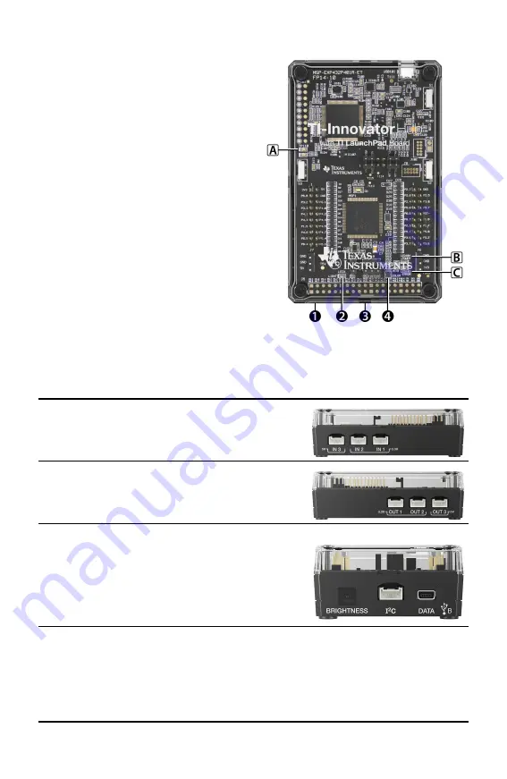
TI-Innovator™ Hub with On-Board
Components

À

  A Light Brightness Sensor at the bottom

of the Hub can be read as
"BRIGHTNESS" in Hub command strings.

Á

  Red LED is addressable as "LIGHT" in

Hub command strings.

Â

  Speaker (at back of Hub, not shown) is

addressable as "SOUND" in Hub
command strings.

Ã

  Red-Green-Blue LED is addressable as

"COLOR" in Hub command strings.

Also visible on the face of the Hub are:

A

Green auxiliary power LED

B

Green power LED,

C

Red error LED.

Built-in Ports

Left side - Three ports for collecting data or status
from input modules:

IN 1

and

IN 2

provide 3.3V power.

IN 3

provides 5V power.

Right side - Three ports for controlling output
modules:

OUT 1

and

OUT 2

provide 3.3V power.

OUT 3

provides 5V power.

Bottom - Light Brightness Sensor (described earlier)
and two ports:

I

2

C

port connects to peripherals that use the I

2

C

communication protocol.

DATA

 Mini-B port, used with the appropriate

cable, connects to a compatible graphing
calculator or computer for data and power.

2

Summary of Contents for TI-Innovator Hub

Page 1: ...TI Innovator Hub with TI LaunchPad Board Setup Guide Learn more about TI Technology through the online help at education ti com eguide ...

Page 2: ...r Technology eGuide Parts of this document refer you to the TI Innovator Technology eGuide for more details The eGuide is a Web based source of TI Innovator information including Programming with the TI CE Family of Graphing Calculators and TI Nspire Technology including sample programs Available I O Modules and their commands Available breadboard components and their commands Available TI RGB Arr...

Page 3: ... Hub 3 Connecting to a Graphing Calculator 4 Connecting to a Computer Running TI Nspire CX Software 5 Using an Auxiliary Power Source 5 Connecting the Power Source 6 General Precautions for the TI Innovator Hub 7 TI Innovator Hub 7 Breadboard Connector on the Hub 7 General Information 8 Online Help 8 Contact TI Support 8 Service and Warranty 8 FCC Statement 8 Canada Declaration 8 iii ...

Page 4: ...p which contains the Hub menu TI Nspire CX or TI Nspire CX CAS handheld with operating system version 4 5 or later installed TI Nspire computer software version 4 5 or later TI Innovator Hub Communicates with the host the Hub on board components and connected external components It also distributes power to external components TI Innovator Components These components sold separately include sensor...

Page 5: ... of the Hub are A Green auxiliary power LED B Green power LED C Red error LED Built in Ports Left side Three ports for collecting data or status from input modules IN 1 and IN 2 provide 3 3V power IN 3 provides 5V power Right side Three ports for controlling output modules OUT 1 and OUT 2 provide 3 3V power OUT 3 provides 5V power Bottom Light Brightness Sensor described earlier and two ports I2C ...

Page 6: ...to Mini B Connects the Hub to a computer running TI Nspire CX Software  USB Standard A to Micro Connects the PWR port of the Hub to a TI approved power source required by some peripherals Auxiliary Power TI Wall Charger Supplies power through the TI Innovator Hub for components such as motors that require additional power The optional External Battery Pack can also provide auxiliary power Note An...

Page 7: ... B cable Each end of this cable is embossed with a letter 2 Insert the B connector into the DATA port at the bottom of the TI Innovator Hub 3 Insert the free end of the cable the A connector into the USB port on the calculator Hub connected to TI CE Graphing Calculator Hub connected to TI Nspire CX Handheld 4 Turn on the calculator if it is not already on The power LED on the Hub glows green to sh...

Page 8: ...ator Hub and its connected components draw power from the host calculator or computer through the DATA connector Certain components such as the optional Servo Motor require more power than a calculator can provide reliably The PWR connector on the Hub lets you connect an auxiliary power source You can use the TI Wall Charger or the External Battery Pack TI Wall Charger included with the Hub Plugs ...

Page 9: ...ble 2 Insert the Micro connector into the PWR connector at the top of the Hub 3 Insert the free end of the cable the A connector into the USB port on the power source 4 Turn on the power source If using the TI Wall Charger plug it into a wall socket If using the External Battery Pack press the power button An auxiliary power LED on the Hub glows to show that the Hub is receiving auxiliary power 5 ...

Page 10: ...eceiving power from the Hub do not exceed the Hub s 1 amp power limit Avoid using the Hub to control AC electricity Breadboard Connector on the Hub Do not insert the leads of LEDs and other components directly into the Hub s Breadboard Connector Assemble the components on the breadboard and use the provided jumper cables to connect the breadboard to the Hub Do not connect the 5V receptacle pin on ...

Page 11: ...nce will not occur in a particular installation If this device does cause harmful interference to radio or television reception which can be determined by turning the device off and on the user is encouraged to try to correct the interference by one or more of the following measures Reorient or relocate the receiving antenna Increase the separation between the device and receiver Connect the devic...

Page 12: ...Instruments U S A 12500 TI Blvd Dallas TX 75243 Texas Instruments Holland B V Bolwerkdok 2 3433 KN Nieuwegein The Netherlands Printed by 2019 Texas Instruments education ti com ti cares ENGLISH STEM OM 1L1 D ...

Reviews: