25 July 1996
23 mm Transponder Reference Manual
Page 15 of 22
3 dB
f
Res
f
U
Pick-up
coil
f
Figure 14: Determination of the resonance frequency and -3dB bandwidth by monitoring
the pick-up coil voltage
7.2 Measurement Set-Up: Powering Field Strength
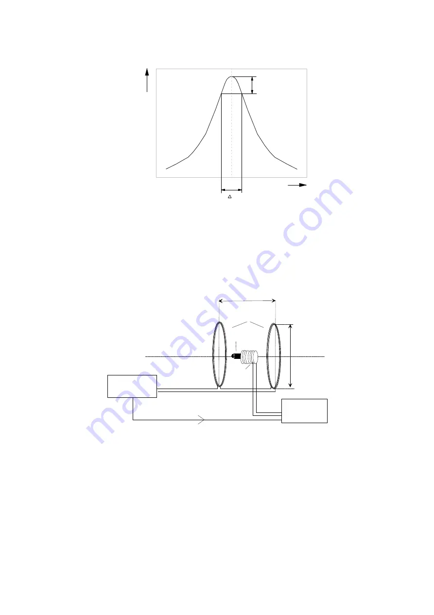
The following set-up is used to determine the minimum required powering field strength.
ANTENNA AXIS
PICK-UP
COIL
SIGNAL
GENERATOR
d/2
d
COILS
OSCILLOSCOPE
Trigger
TRANSPONDER
Figure 15: Test set-up for powering field strength determination
The field between both serial connected coils is homogeneous, due to the fact that the aperture is
built according to the Helmholtz set-up. The circular coils are positioned in parallel on one axis.
The distance between the coils is half the coil diameter. The transponder is positioned in the middle
of the coil axis.


