Digital Interface Circuits
4-3
Analog and Digital Interface
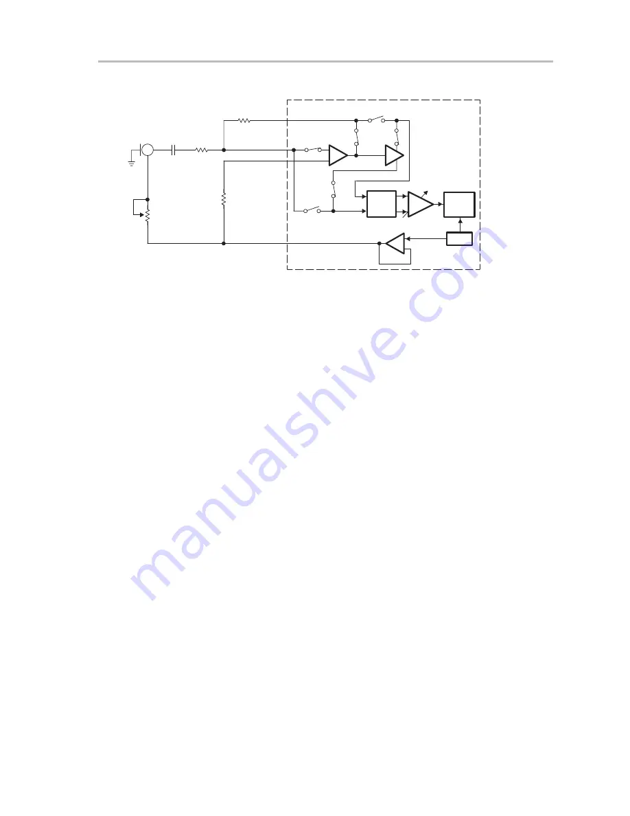
Figure 4–1. Microphone Interface With TLV320AIC10/11
Sigma-
Delta
ADC
PGA
TLV320AIC10
Anti-
Aliasing
Filter
Vref
AURXFP
Electret
Microphone
MIC_BIAS
VMID
10 k
Ω
AURXM
AURXCP
20 k
Ω
S2D
+
–
1 k
Ω
10 k
Ω
0.1
µ
F
Microphone Interface
RP1
4.1.4
Speaker Interface
The DAC signals of AIC10/11 U1 and U2 can be output to the two speaker
drivers on the EVM board. A speaker driver circuit contains a TI TPA4861
audio power amplifier capable of delivering 1 W continuous average power
into an 8
Ω
load, typically a speaker. By setting jumpers W2 and W3 to position
1–2, the analog output of U1 is routed to the speaker driver. Similarly, by
populating jumpers W39 and W60, the device analog output of U2 is routed
to its onboard speaker driver. Connect external speakers to J5 (from U1) and
J6 (from U2).
4.2
Digital Interface Circuits
This section describes the digital interface circuits of the EVM. Additional
information for digital configuration and setup circuits is given in Chapter 3.
4.2.1
C5402 DSK McBSP Interface
Figure 4–2 illustrates the connection and data flow direction for C54xx DSP
McBSP and TLV320AIC10/11 interface. The AIC10/11 devices U1 and U2 on
the EVM board are designed to connect to the McBSP ports of the C5402 DSP
via connector J10 (80 pin). Table 2–4 lists the interface connections for the
EVM connector to the C5402 DSK motherboard.
Summary of Contents for TLV320AIC10 EVM
Page 1: ... January 2001 AAP Data Converters User s Guide SLWU003D ...
Page 4: ...iv ...
Page 12: ...1 6 ...
Page 34: ...5 6 ...
Page 38: ...Printed Circuit Board Rev C 6 4 Figure 6 3 Printed Circuit Board Layer 1 Rev C ...
Page 40: ...Printed Circuit Board Rev C 6 6 Figure 6 5 Printed Circuit Board Layer 3 Rev C ...
Page 42: ...Printed Circuit Board Rev C 6 8 Figure 6 7 Printed Circuit Board Layer 5 Rev C ...


