I/O Connector and Signals
3-5
Operation
3.3
I/O Connector and Signals
The various connectors on the AIC26EVM are described in this section.
3.3.1
Audio Connectors
The AIC26 audio inputs and outputs are routed through these stereo
(TIP/RING/SLEEVE) 3.5-mm jacks. Note the polarity of the channel
assignments for these connectors.
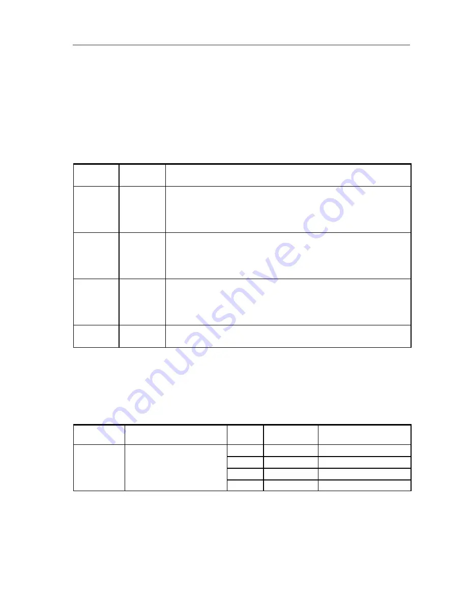
Table 3−3. Audio Connectors
Reference
Designator
Name
Description
J5
Mic In
Microphone input
-
tip = mic bias voltage (and MIC input−, if different)
-
ring = mic input+
-
sleeve = ground
J6
Headphone
Out
Stereo headphone audio outputs
-
tip = left channel
-
ring = right channel
-
sleeve = virtual ground
J7
Line Out
Stereo headphone output with ac coupling
-
tip = left channel
-
ring = right channel
-
sleeve = ground
J13
Loudspeaker
When the AIC26 output drive is in high power mode, an 8-
Ω
loudspeaker can
be connected to J13.
3.3.2
USB Interface Connector
Connection to a USB cable from a PC is made through J8, a standard USB
type B receptacle.
Table 3−4. USB Interface Connector
Reference
Designator
Description
Pin
Number
Signal Name
Function
1
VCC
+ 5-V supply from USB
2
D−
– Differential USB signal
J8
USB slave connection to PC
3
D+
+ Differential USB signal
4
GND
Ground
Summary of Contents for TLV320AIC26EVM
Page 12: ...1 4 THIS PAGE INTENTIONALLY LEFT BLANK ...
Page 15: ...Quick Start 2 3 Getting Started Figure 2 1 Default Software Screen ...
Page 16: ...2 4 THIS PAGE INTENTIONALLY LEFT BLANK ...
Page 26: ...Program Description 3 10 Figure 3 1 Data Acquisition Screen With ADC Registers Reading ...
Page 28: ...Program Description 3 12 Figure 3 3 Data Acquisition Screen With Boost Filter Parameters ...
Page 37: ...3 21 Operation THIS PAGE INTENTIONALLY LEFT BLANK ...
Page 39: ...Component Locations 4 2 4 1 Component Locations ...


