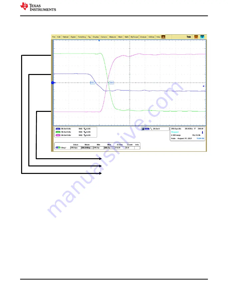
Next is a scope shot capture of the inputs and outputs described in the propagation delay procedure. High to
Low propagation delay is defined as when the signal generator input (IN+) reaches 0 V to when OUT- reaches 0
V. The propagation delay was measured at approximately 206 ps with the setup described.
Channel 4: OUT-
Channel 1: 100mV peak-to-peak VOD 50mV VUD 50mV 10MHz
Channel 3: OUT+
Figure 5-2. Quick Start Example
How to Make a TPHL Propagation Delay Measurement With Split Supplies
SNOU184 – NOVEMBER 2021
TLV3801EVM User’s Guide
7
Copyright © 2021 Texas Instruments Incorporated


