6 Board Setup
6.1 Supply Voltage
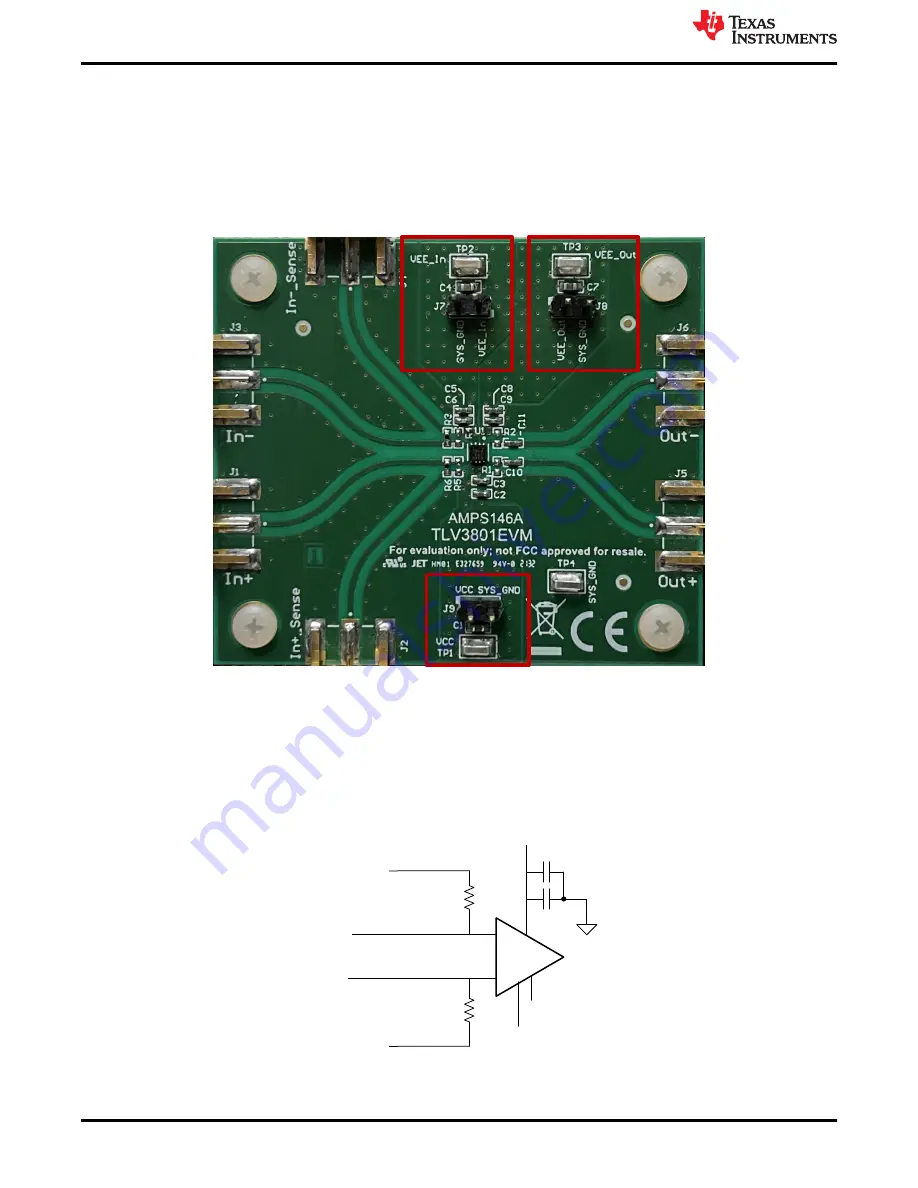
The TLV3801EVM can operate from a single supply or split supply configuration. If using the a single supply
(VEE_In and VEE_Out shorted to GND), then the recommended voltage range is from 2.7-V to 5.5-V. When a
split supply configuration is used, then VCC - VEE (applies to both VEE_In and VEE_Out) has a range of 2.7-V
to 5.5-V and VCC - GND has a range of 2.4-V to 5.25-V. Connect VCC, VEE_In, and VEE_Out using TP1, TP2,
and TP3 respectively.
Figure 6-1. TLV3801EVM Supply Voltage Connection
6.2 Inputs
Resistors R6 and R3 are 0-Ω resistors. The input terminals (IN+ and IN-) have corresponding sense lines so that
the inputs to the device can be terminated on the lines with 50-Ω to an oscilloscope. This allows the input signals
to be observed with minimal loading and distortion. There are also optional input resistors R4 and R5 for direct
50-Ω terminations if required by the input signal generator, otherwise they can be left uninstalled.
R3 0
+
–
R6 0
GND
IN+_SENSE
IN-_SENSE
V
CC
V
EE_Out
V
EE_In
IN+
IN-
Figure 6-2. Input Side Schematic Without Optional Resistors R4 and R5
Board Setup
8
TLV3801EVM User’s Guide
Copyright © 2021 Texas Instruments Incorporated


