TMP006
V
Supply
(Sw3.3-V Power)
DUT
I C Interface
2
Serial Interface (SPI)
10-Pin Female
SM-USB-DIG
Connector
DRDY
LED
Circuitry
10-Pin FFC
Cable
Connector
TMP006EVM Hardware Setup
2.1
Theory of Operation for the TMP006 Test Board
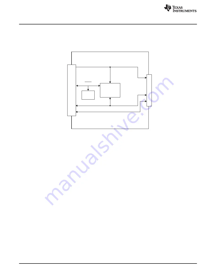
A block diagram of the TMP006 test board hardware setup is shown in
. The TMP006 Test Board
contains connections for the power, I
2
C, SPI, and GPIO signals from the SM-USB-DIG. It also has a
connector that allows other boards to be connected to the TMP006 Test Board to assist with calibrating
the TMP006.
Figure 3. TMP006EVM Board Block Diagram
4
TMP006EVM User Guide and Software Tutorial
SBOU109A
–
May 2011
–
Revised October 2011
Copyright
©
2011, Texas Instruments Incorporated


