Instruction Set Summary
7-4
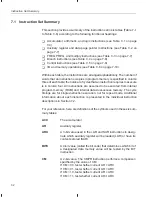
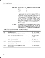
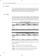
ZLVC ZLVC
Two 4-bit fields — each representing the following conditions:
ACC = 0
Z
ACC < 0
L
Overflow
V
Carry
C
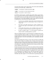
A conditional instruction contains two of these 4-bit fields. The
4-LSB field of the instruction is a mask field. A 1 in the corre-
sponding mask bit indicates that condition is being tested. For
example, to test for ACC
≥
0, the Z and L fields are set, and
the V and C fields are not set. The Z field is set to test the condi-
tion ACC = 0, and the L field is reset to test the condition
ACC
≥
0.The second 4-bit field (bits 4 – 7) indicates the state
of the conditions to test. The conditions possible with these
eight bits are shown in the descriptions for the BCND, CC, and
RETC instructions.
+ 1 word
The second word of a two-word opcode. This second word
contains a 16-bit constant. Depending on the instruction, this
constant is a long immediate value, a program memory ad-
dress, or an address for an I/O port or an I/O-mapped register.
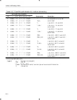
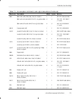
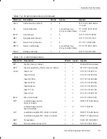
Table 7–1. Accumulator, Arithmetic, and Logic Instructions
Mnemonic
Description
Words Cycles
Opcode
ABS
Absolute value of ACC
1
1
1011 1110 0000 0000
ADD
Add to ACC with shift of 0 to 15, direct or indirect
1
1
0010 SHFT IAAA AAAA
Add to ACC with shift 0 to 15, long immediate
2
2
1011 1111 1001 SHFT
+ 1 word
Add to ACC with shift of 16, direct or indirect
1
1
0110 0001 IAAA AAAA
Add to ACC, short immediate
1
1
1011 1000 IIII IIII
ADDC
Add to ACC with carry, direct or indirect
1
1
0110 0000 IAAA AAAA
ADDS
Add to low ACC with sign-extension suppressed,
direct or indirect
1
1
0110 0010 IAAA AAAA
ADDT
Add to ACC with shift (0 to 15) specified by TREG,
direct or indirect
1
1
0110 0011 IAAA AAAA

