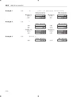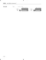
Test Bit
BIT
7-45
Assembly Language Instructions
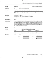
Syntax
BIT
dma, bit code
Direct addressing
BIT
ind, bit code [, ARn]
Indirect addressing
Operands
dma:
7 LSBs of the data-memory address
bit code:
Value from 0 to 15 indicating which bit to test (see Figure 7–1)
n:
Value from 0 to 7 designating the next auxiliary register
ind:
Select one of the following seven options:
* *+ *– *0+ *0– *BR0+ *BR0–
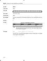
BIT
dma, bit code
15
14
13
12
11
10
9
8
7
6
5
4
3
2
1
0
0
1
0
0
bit code
0
dma
BIT
ind, bit code [ ,ARn ]
15
14
13
12
11
10
9
8
7
6
5
4
3
2
1
0
0
1
0
0
bit code
1
ARU
N
NAR
Note:
ARU, N, and NAR are defined in Section 6.3,
Indirect Addressing Mode (page 6-9).
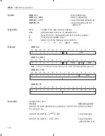
Execution
Increment PC, then ...
(data bit number (15 – bit code))
→
TC
Status Bits
Affects
TC
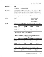
Description
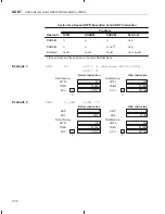
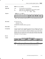
The BIT instruction copies the specified bit of the data-memory value to the TC
bit of status register ST1. Note that the BITT, CMPR, LST #1, and NORM in-
structions also affect the TC bit in ST1. A bit code value is specified that corre-
sponds to a certain bit number of the data-memory value, as shown in
Figure 7–1.
Figure 7–1. Bit Numbers and Their Corresponding Bit Codes for BIT Instruction
Bit code
0
1
2
3
4
5
6
7
8
9
10
11
12
13
14
15
Bit number
15
14
13
12
11
10
9
8
7
6
5
4
3
2
1
0
MSB
Data-memory value
LSB
Words
1
Opcode


