www.ti.com
LINE REGULATION
vs
INPUT VOLTAGE
-0.30
-0.20
-0.10
0
0.10
0.20
0.30
10 12 14 16 18 20 22 24 26 28 30 32 34 36
V - Input Voltage - A
I
Output Regulation - %
I
= 1 A
O
I
= 0 A
O
I
= 2 A
O
2.4
Load Transients
t - Time = 200
μ
s/Div
I
A/Div
OUT
= 500 m
V
OUT
= 50 mV/Div (AC Coupled)
Test Setup and Results
Figure 3. Line Regulation
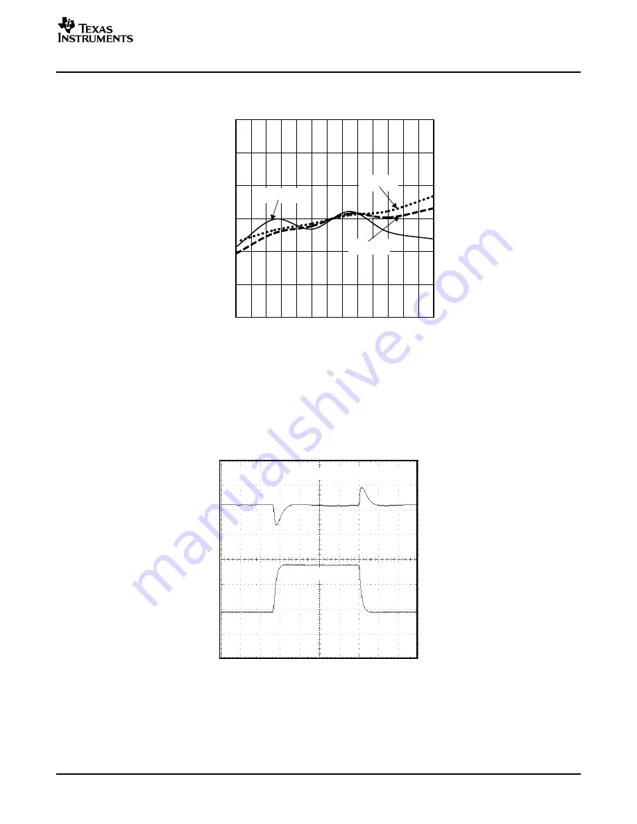
The TPS5420EVM-175 response to load transients is shown in
Figure 4
. The current step is from 25% to
75% of maximum rated load. Total peak-to-peak voltage variation is as shown, including ripple and noise
on the output.
Figure 4. Load Transient Response, TPS5420
SLVU163 – April 2006
TPS5420EVM-175 SWIFT™ Regulator Evaluation Module
5
Submit Documentation Feedback


