10
SLVSDC2B – FEBRUARY 2016 – REVISED AUGUST 2016
Product Folder Links:
Copyright © 2016, Texas Instruments Incorporated
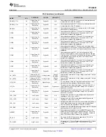
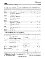
7.6 Power Supervisor Characteristics
Recommended operating conditions; T
A
= –40°C to +105°C unless otherwise noted
PARAMETER
TEST CONDITIONS
MIN
TYP
MAX
UNIT
UV_LDO3V3
Undervoltage threshold for LDO_3V3. Locks out 1.8-V
LDOs
LDO_3V3 rising
2.2
2.325
2.45
V
UVH_LDO3V3
Undervoltage hysteresis for LDO_3V3
LDO_3V3 falling
20
80
150
mV
UV_VBUS_LDO
Undervoltage threshold for VBUS to enable LDO
VBUS rising
3.35
3.75
3.95
V
UVH_VBUS_LDO
Undervoltage hysteresis for VBUS to enable LDO
VBUS falling
20
80
150
mV
UV_PCBL
Undervoltage threshold for PP_CABLE
PP_CABLE rising
2.5
2.625
2.75
V
UVH_PCBL
Undervoltage hysteresis for PP_PCABLE
PP_CABLE falling
20
50
80
mV
UV_5V0
Undervoltage threshold for PP_5V0
PP_5V0 rising
3.5
3.725
3.95
V
UVH_5V0
Undervoltage hysteresis for PP_P5V0
PP_5V0 falling
20
80
150
mV
OV_VBUS
Overvoltage threshold for VBUS. This value is a 6-bit
programmable threshold
VBUS rising
5
24
V
OVLSB_VBUS
Overvoltage threshold step for VBUS. This value is the
LSB of the programmable threshold
VBUS rising
328
mV
OVH_VBUS
Overvoltage hysteresis for VBUS
VBUS falling, % of OV_VBUS
0.9%
1.3%
1.7%
UV_VBUS
Undervoltage threshold for VBUS. This value is a 6-bit
programmable threshold
VBUS falling
2.5
18.21
V
UVLSB_VBUS
Undervoltage threshold step for VBUS. This value is the
LSB of the programmable threshold
VBUS falling
249
mV
UVH_VBUS
Undervoltage hysteresis for VBUS
VBUS rising, % of UV_VBUS
0.9%
1.3%
1.7%
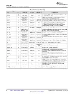
UVR_RST3V3
Configurable under-voltage threshold for VRSTZ_3V3
rising. De-asserts RESETZ
VIN_3V3 and VRSTZ_3V3
rising (default setting)
2.613
2.75
2.888
V
UVRH_RST3V3
Under-voltage hysteresis for VRST_3V3 falling. Asserts
RESETZ
VIN_3V3 and VRSTZ_3V3
falling
30
50
mV
TUVRASSERT
Delay from falling or MRESET assertion to RESETZ
asserting low
75
μ
s
TUVRDELAY
Configurable delay from to RESETZ de-assertion
0
161.3
ms
(1)
Application code can result in other power consumption measurements by adjusting enabled circuitry and clock rates. Application code
also provisions the wake=up mechanisms (for example, I
2
C activity and GPIO activity).
(2)
Sleep is defined as Type-C cable detect activated as DFP or UFP, internal power management and supervisory functions active.
(3)
Idle is defined as Type-C cable detect activated as DFP or UFP, internal power management and supervisory functions active, and the
digital core is clocked at 4 MHz.
(4)
Active is defined as Type-C cable detect activated as DFP or UFP, internal power management and supervisory functions active, all
core functionality active, and the digital core is clocked at 12 MHz.
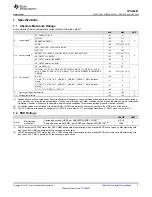
7.7 Power Consumption Characteristics
Recommended operating conditions; T
A
= 25°C (Room temperature) unless otherwise noted
(1)
PARAMETER
TEST CONDITIONS
MIN
TYP
MAX
UNIT
IVIN_3V3
Sleep
(2)
VIN_3V3 = VDDIO = 3.45 V, VBUS = 0,
PPCABLE = 0; 100-kHz oscillator running
62
µA
Idle
(3)
VIN_3V3 = VDDIO = 3.45 V, VBUS=0, PPCABLE
= 0; 100-kHz oscillator running,
48-MHz oscillator running
2.5
mA
Active
(4)
VIN_3V3 = VDDIO = 3.45 V, VBUS = 0,
PPCABLE = 0; 100-kHz oscillator running,
48-MHz oscillator running
6.0
mA


