5 A
RSENSE
10 mΩ ± 1%
NMOS
HV Gate Control and Sense
SENSEP
SENSEN
HV_GA
TE1
HV_GA
TE2
VBUS
PP_EXT
40
SLVSDC2B – FEBRUARY 2016 – REVISED AUGUST 2016
Product Folder Links:
Copyright © 2016, Texas Instruments Incorporated
be used to source current from PP_HV to VBUS when the TPS65981 is acting as a power source and the
external path may be used to sink current from VBUS to PP_EXT to charge a battery when the TPS65981 is
acting as a sink. The internal and external paths must never be used in parallel to source current at the same
time or sink current at the same time. The current limiting function will not function properly in this case and may
become unstable.
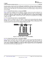
9.3.3.11 External HV Power Switch as a Source with RSENSE
shows the configuration when the TPS65981 is acting as a source for the external switch path. The
external FETs must be connected in a common-drain configuration and will not work in a common source
configuration. In this mode, current is sourced to VBUS. RSENSE provides an accurate current measurement
and is used to initiate the current limiting feature of the external power path. The voltage between SENSEP
(PP_EXT) and SENSEN (VBUS) is sensed to block reverse current flow. This measurement is also digitally
readable via the ADC.
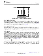
9.3.3.12 External HV Power Switch as a Sink With RSENSE
shows the configuration when the TPS65981 is acting as a sink for the external switch path with
RSENSE used to sense current. Acting as a sink, the voltage between SENSEP (VBUS) and SENSEN
(PP_EXT) is sensed to provide an accurate current measurement and initiate the current limiting feature of the
external power path. This measurement is also digitally readable via the ADC.
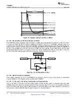
Figure 29. External HV Switch as a Sink With RSENSE
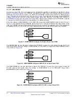
9.3.3.13 External HV Power Switch as a Sink Without RSENSE
shows the configuration when the TPS65981 is acting as a sink for the external switch path without an
RSENSE resistor. In this mode, current is sunk from VBUS to an internal system power node, referred to as
PP_EXT. This is used for charging a battery or for providing a supply voltage for a bus-powered device. To block
reverse current, the VBUS and SENSEP pins monitor the voltage across the NFETs. To ensure that SENSEN
does not float, tie SENSEP to SENSEN in this configuration. When configured in this mode, the digital readout
from current from the ADC will be approximately zero.


