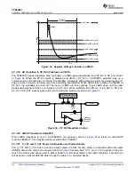
SWD_CLK
SWD_DATA
R_OSC
GPIO0,2-8
BUSPOWERZ
I2C_SDA
I2C_SCL
I2C_IRQZ
SPI_CLK
SPI_MOSI
SPI_MISO
SPI_SSZ
Digital Core
SWD
ADC
Temp
Sense
USB EP
Phy
Signals
into ADC
USB EP
Thermal
Shutdown
CBL_DET
Bias CTL
and USB-PD
SPI
Phy
USB PD
Port
OSC
Debug
Port
DEBUG_CTL1
DEBUG_CTL2
I C to
2
System Control
SPI to
Flash
RESETZ
MRESET
ADC
Read
I C
2
I C
2
Copyright © 2016, Texas Instruments Incorporated
55
SLVSDC2B – FEBRUARY 2016 – REVISED AUGUST 2016
Product Folder Links:
Copyright © 2016, Texas Instruments Incorporated
9.3.6 Digital Core
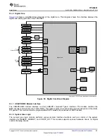
shows a simplified block diagram of the digital core. This diagram shows the interface between the
digital and analog portions of the TPS65981.
Figure 50. Digital Core Block Diagram
9.3.7 USB-PD BMC Modem Interface
The USB-PD BMC modem interface is a fully USB-PD compliant Type-C interface. The modem contains the
BMC encoder and decoder, the TX/Rx FIFOs, the packet engine for construction and deconstruction of the USB-
PD packet. This module contains programmable SOP values and processes all SOP headers.
9.3.8 System Glue Logic
The system glue logic module performs various system interface functions such as control of the system
interface for RESETZ, MRESET, and VRSTZ_3V3. This module supports various hardware timers for digital
control of analog circuits.

