8
SLVSDC2B – FEBRUARY 2016 – REVISED AUGUST 2016
Product Folder Links:
Copyright © 2016, Texas Instruments Incorporated
(1)
All voltage values are with respect to network GND. All GND pins must be connected directly to the GND plane of the board.
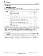
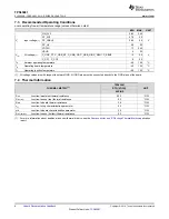
7.3 Recommended Operating Conditions
over operating free-air temperature range (unless otherwise noted)
MIN
MAX
UNIT
V
I
Input voltage
(1)
VIN_3V3
2.85
3.45
V
PP_5V0
4.75
5.5
PP_CABLE
2.95
5.5
PP_HV
4.5
22
VDDIO
1.7
3.45
V
IO
I/O voltage
(1)
VBUS
4
22
V
C_USB_PT, C_USB_NT, C_USB_PB, C_USB_NB, C_SBU1, C_SBU2
–2
5.5
C_CC1, C_CC2
0
5.5
T
A
Ambient operating temperature
–40
105
°C
T
B
Operating board temperature
–40
120
°C
T
J
Operating junction temperature
–40
125
°C
(1)
For more information about traditional and new thermal metrics, see the
Semiconductor and IC Package Thermal Metrics
application
report.
7.4 Thermal Information
THERMAL METRIC
(1)
TPS65981
UNIT
RTQ (VQFN)
56 PINS
R
θ
JA
Junction-to-ambient thermal resistance
25.2
°C/W
R
θ
JC(top)
Junction-to-case (top) thermal resistance
9.3
°C/W
R
θ
JB
Junction-to-board thermal resistance
3.6
°C/W
ψ
JT
Junction-to-top characterization parameter
0.2
°C/W
ψ
JB
Junction-to-board characterization parameter
3.5
°C/W
R
θ
JC(bottom)
Junction-to-case (bottom) thermal resistance
0.5
°C/W


