+
100 kΩ
10 kΩ
1.8 V
DC Barrel Jack Voltage
Barrel Jack Detect/
PFET Enable
80
SLVSDC2B – FEBRUARY 2016 – REVISED AUGUST 2016
Product Folder Links:
Copyright © 2016, Texas Instruments Incorporated
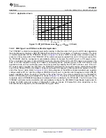
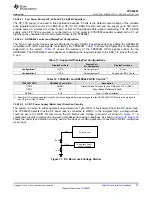
Figure 78. Barrel Jack Detect Comparator
This detect signal is used to determine if the barrel jack is present to support the 20 V PD power contracts and to
hand-off charging from barrel jack to Type-C or Type-C to barrel jack. When the DC barrel jack is detected the
TPS65981 at the Type-C port will not request power as a USB PD sink and the system will be able to support a
5-20 V source power contract to another device. When the DC Barrel Jack is disconnected the TPS65981 will
exit any 20 V source power contract and re-negotiate a power contract as a sink. When the DC Barrel Jack is re-
connected the TPS65981 will send updated source capabilities and re-negotiate a power contract if possible.
10.2.2.2.4
TPS65981 Control of Variable Buck Regulator Output Voltage (PP_HV)
The Type-C port in this design supports the 4 standard discrete source voltages in USB PD (5 V, 9 V, 15 V, and
20 V) by adding the
DC-DC hysteretic PFET buck controller with GPIOs controlled by the TPS65981
that enables the LM3489 and modifies the output voltage that is supplied to VBUS through the internal PP_HV
power switch. In
, the enabled (EN) pin of the LM3489 is controlled by DBG_CTL1 which is mapped to
the Plug Event GPIO so that whenever a Type-C plug occurs the voltage regulator will generate the 5-V default
output voltage for sourcing Type-C and PDO1 power. The default voltage is set by a resistor divider (R
FB1
and
R
FB2
) with the center tap connected to the feedback pin (FB) of the LM3489. The TPS65981 modifies the output
voltage when a high voltage PD contract is negotiated by forcing a GPIO output high and switching in a third
resistor in parallel with R
FB2
in the feedback circuit. In
, GPIO6 indicates a 9-V PD contract (PDO2),
GPIO7 indicates a 15-V contract (PDO3), and GPIO8 indicates a 20-V contract (PDO4). The LM3489 was
selected because the architecture allows 100% duty-cycle operation, where the only additional power loss in the
system is from the R
DS,ON
of the PFET used in the regulator circuit.
10.2.2.2.5
TPS65981 and System Controller Interaction
The TPS65981 features an I
2
C slave port, where a system controller has the ability to write to the I
2
C slave port.
The I
2
C port has an I
2
C interrupt that will inform the system controller that a change has happened in the system.
This allows the system controller to dynamically budget power and reconfigures a port’s capabilities dependent
on current state of the system. The system controller is also used for updating the TPS65981 firmware over I
2
C,
where a connected host or the application processor loads the Firmware update to the system controller and
then the system controller updates firmware stored in the SPI Flash memory via I
2
C writes to the TPS65981. In a
dock or monitor application, the video scalar is commonly a processor and the I
2
C master capable of acting as
the system controller for the TPS65981.


