A.2 Rev.A - Setup
This section describes how to properly use the TPSM8282xEVM-080 Rev.A.
A.2.1 Rev.A - Setup
To operate the EVM, set jumper J3 between ON and EN to turn on the device as shown in
.
Connect the input supply to J1 and connect the load to J2.
A.2.2 Rev.A - Input/Output Connector Descriptions
J1, Pin 1 and 2 – VIN
Positive input connection from the input supply for the EVM.
J1, Pin 3 and 4 – S+/S–
Input voltage sense connections. Measure the input voltage at this point.
J1, Pin 5 and 6 – GND
Input return connection from the input supply for the EVM.
J2, Pin 1 and 2 – VOUT
Output voltage connection
J2, Pin 3 and 4 – S+/S–
Output voltage sense connections. Measure the output voltage at this point.
J2, Pin 5 and 6 – GND
Output return connection
J3 – EN
EN pin input jumper. Place the supplied jumper across ON and EN to turn on the module. Place the
jumper across OFF and EN to turn off the IC.
J4 – PG/GND
The PG output appears on pin 1 of this header with ground on pin 2.
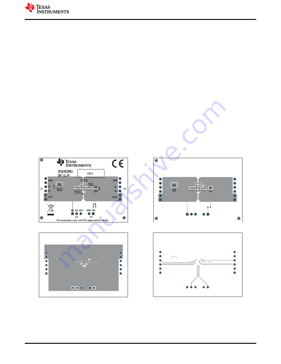
A.3 Rev.A - Board Layout
This section provides the TPSM8282xEVM-080 Revision A board layout and illustrations in
through
.
Figure A-1. Rev.A - Top Assembly
Figure A-2. Rev.A - Top Layer
Figure A-3. Rev.A - Signal Layer 1
Figure A-4. Rev.A - Signal Layer 2
Appendix - Rev.A EVM
SLVUBR5D – AUGUST 2019 – REVISED NOVEMBER 2021
TPSM8282xEVM-080 and TPSM8282xAEVM-127 Evaluation Modules
9
Copyright © 2021 Texas Instruments Incorporated


