5.5.10 Removing/Replacing the LED Board
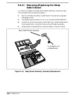
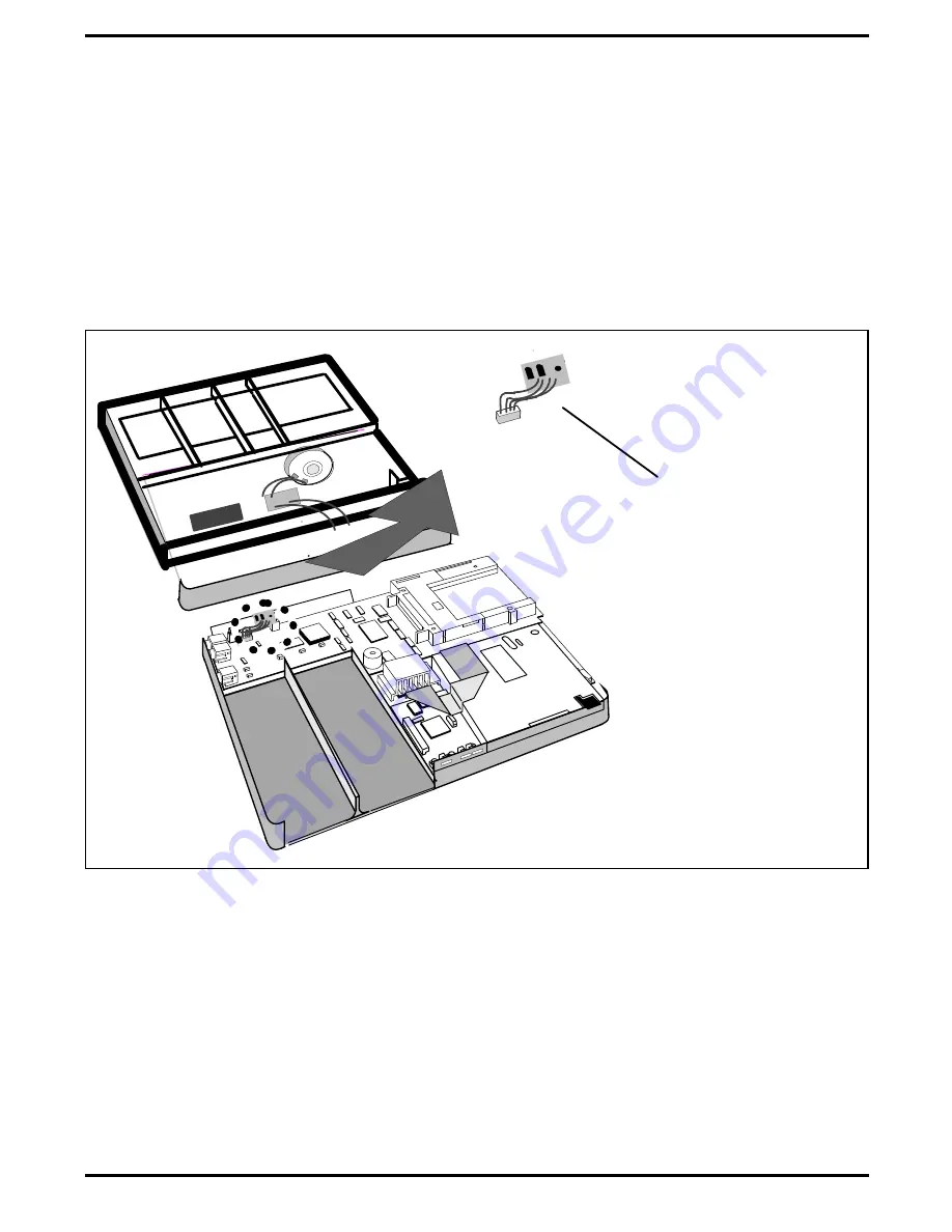
To remove and replace the LED Board Assembly, reference Figure 5-13 and
perform the following procedure:
1.
Open up the base assembly as described in the previous paragraph
(Paragraph 5.5.6).
2.
Unplug the cable connector from J11 on the Sound/PCMCIA Board.
3.
Remove the screw securing the LED Board to the metal bracket above the
Expansion Bus Connector. Remove the LED Board assembly.
4.
Replacement is essentially the reverse of Steps 1 through 4 above.
LED Board Assembly
Figure 5-13 The LED Board, Removal/Replacement
Field Service
5-19
Summary of Contents for TravelMate 5000 Series
Page 1: ...Maintenance Manual TravelMate 5000 Series Notebook Computers 9786166 0001 March 1995 ...
Page 47: ...Figure 1 16 TM5000 Series Functional Block Diagram 1 30 General Description ...
Page 95: ...Figure 4 2 Notebook Detailed Block Diagram Troubleshooting Procedures 4 3 ...
Page 149: ...Figure 6 4 Main Board P54 75MHz P N 9798803 0001 Sheet 2 of 2 6 14 Illustrated Parts Listing ...
Page 172: ...Figure 6 7 Keyscan Board P N 9786209 0001 Illustrated Parts Listing 6 37 ...
Page 180: ...Figure 6 11 Inverter Board P N 9786134 0001 Illustrated Parts Listing 6 45 ...
Page 185: ...Figure 6 12 DAB Board P N 9786273 0001 6 50 Illustrated Parts Listing ...
Page 228: ...Figure 7 5 Figure 7 5 IR Board P N 9798813 Logic Diagram Sheet 1 of 2 7 42 Schematic Diagrams ...
Page 229: ...Figure 7 5 Figure 7 5 IR Board P N 9798813 Logic Diagram Sheet 2 of 2 Schematic Diagrams 7 43 ...
Page 239: ...Figure A 1 Code Page 437 United States A 2 Character Sets ...
Page 240: ...Figure A 2 Code Page 850 Multilingual Character Sets A 3 ...
Page 241: ...Figure A 3 Code Page 863 Canadian French A 4 Character Sets ...
Page 242: ...Figure A 4 Code Page 865 Nordic Character Sets A 5 ...
Page 286: ...Printed in U S A ...


