2.4.3
Installing the EZ-Dock /EZ-Dock Plus
Port Replicator (Option)
n
Note:
Skip this paragraph if not installing a port replicator option at this
time.
The optional Port Replicator is installed as follows:
1.
Remove the port replicator and any accessories from its shipping carton .
2.
Disconnect the AC Adapter from the notebook (if attached).
3.
Clear an area on your workstation surface to permit the notebook and
Port Replicator to rest on the work surface during the docking
procedure.
4.
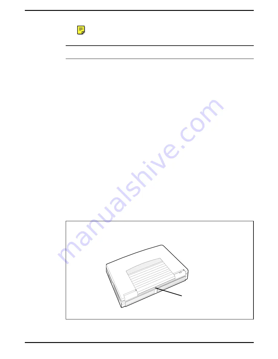
Press the rear connector door release button on the rear of the notebook
as shown in Figure 2-7.
5.
Attach the port replicator to the notebook as shown in Figure 2-8 and
described in following steps.
6.
Lift the lever on top of the Port Replicator so that the guide pin plate is
extended (see Figure 2-8).
7.
Carefully match the holes on the underside of the notebook with guide
pins portruding from the Port Replicator.
8.
Press the lever on top of the Port Replicator so that the notebook fits
snugly against the Port Replicator.
9.
Refer to Figure 1-8 for Port Replicator connector assignments. Install
additional desktop devices/LANs/etc. as required.
10.
Install the AC Power Adapter to the power connector on the Port
Replicator as shown Figure 2-8.
Rear Cover Doors
Release Button
Figure 2-7 Opening the Notebook Connector Covers
Installation
2-9
Summary of Contents for TravelMate 5000 Series
Page 1: ...Maintenance Manual TravelMate 5000 Series Notebook Computers 9786166 0001 March 1995 ...
Page 47: ...Figure 1 16 TM5000 Series Functional Block Diagram 1 30 General Description ...
Page 95: ...Figure 4 2 Notebook Detailed Block Diagram Troubleshooting Procedures 4 3 ...
Page 149: ...Figure 6 4 Main Board P54 75MHz P N 9798803 0001 Sheet 2 of 2 6 14 Illustrated Parts Listing ...
Page 172: ...Figure 6 7 Keyscan Board P N 9786209 0001 Illustrated Parts Listing 6 37 ...
Page 180: ...Figure 6 11 Inverter Board P N 9786134 0001 Illustrated Parts Listing 6 45 ...
Page 185: ...Figure 6 12 DAB Board P N 9786273 0001 6 50 Illustrated Parts Listing ...
Page 228: ...Figure 7 5 Figure 7 5 IR Board P N 9798813 Logic Diagram Sheet 1 of 2 7 42 Schematic Diagrams ...
Page 229: ...Figure 7 5 Figure 7 5 IR Board P N 9798813 Logic Diagram Sheet 2 of 2 Schematic Diagrams 7 43 ...
Page 239: ...Figure A 1 Code Page 437 United States A 2 Character Sets ...
Page 240: ...Figure A 2 Code Page 850 Multilingual Character Sets A 3 ...
Page 241: ...Figure A 3 Code Page 863 Canadian French A 4 Character Sets ...
Page 242: ...Figure A 4 Code Page 865 Nordic Character Sets A 5 ...
Page 286: ...Printed in U S A ...


