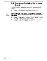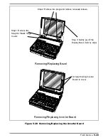
5.5.16 Removing and Replacing the LCD
Cover Assembly
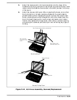
To remove the LCD Cover Assembly with LCD Panel, Microphone, DAB,
Inverter Board, Cover Plastics and Video Driver Board components , refer to
Figure 5-19 and use the following procedure:
1.
Turn off the computer, remove the battery packs and disconnect the ac
power adapter (if it is attached).
2.
Remove the LCD bezel as described in the previous paragraph.
c
Caution: If the notebook is powered up with the LCD bezel removed,
you can be exposed to high voltages which could result in shock and
equipment damage. Ensure that the batteries and AC adapter are re-
moved from the notebook when working on the LCD/Display assembly.
3.
On the original Cover Assembly, peel back the DAB Board insulator and
disconnect the two video cable connectors from the front of the DAB
Board (coming from the Main Board). Also remove the right side
screw and disconnect the grounding strap.
4.
Disconnect the microphone cable and remove the four screws holding the
Cover-Display hinges to the base and remove the old Cover Assembly.
Also secure the grounding strap underneath the DAB board with the
right side screw that secures the DAB board.
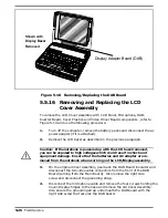
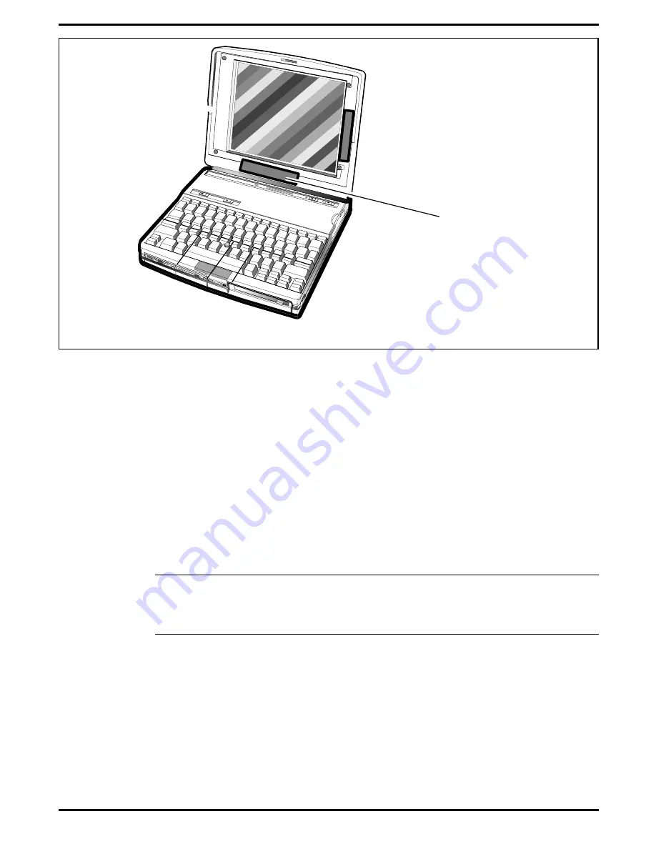
Shown with
Display Bezel
Removed
Display Adapter Board (DAB)
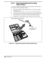
Figure 5-18 Removing/Replacing the DAB Board
5-26
Field Service
Summary of Contents for TravelMate 5000 Series
Page 1: ...Maintenance Manual TravelMate 5000 Series Notebook Computers 9786166 0001 March 1995 ...
Page 47: ...Figure 1 16 TM5000 Series Functional Block Diagram 1 30 General Description ...
Page 95: ...Figure 4 2 Notebook Detailed Block Diagram Troubleshooting Procedures 4 3 ...
Page 149: ...Figure 6 4 Main Board P54 75MHz P N 9798803 0001 Sheet 2 of 2 6 14 Illustrated Parts Listing ...
Page 172: ...Figure 6 7 Keyscan Board P N 9786209 0001 Illustrated Parts Listing 6 37 ...
Page 180: ...Figure 6 11 Inverter Board P N 9786134 0001 Illustrated Parts Listing 6 45 ...
Page 185: ...Figure 6 12 DAB Board P N 9786273 0001 6 50 Illustrated Parts Listing ...
Page 228: ...Figure 7 5 Figure 7 5 IR Board P N 9798813 Logic Diagram Sheet 1 of 2 7 42 Schematic Diagrams ...
Page 229: ...Figure 7 5 Figure 7 5 IR Board P N 9798813 Logic Diagram Sheet 2 of 2 Schematic Diagrams 7 43 ...
Page 239: ...Figure A 1 Code Page 437 United States A 2 Character Sets ...
Page 240: ...Figure A 2 Code Page 850 Multilingual Character Sets A 3 ...
Page 241: ...Figure A 3 Code Page 863 Canadian French A 4 Character Sets ...
Page 242: ...Figure A 4 Code Page 865 Nordic Character Sets A 5 ...
Page 286: ...Printed in U S A ...


