1.7
Notebook Physical Description
The TravelMate 5000 Series Notebooks are modular in design and can be
disassembled for maintenance purposes using a set of TORX
TM
head,
Phillips head, and straight slot screwdrivers as described in Section 5 of
this manual.
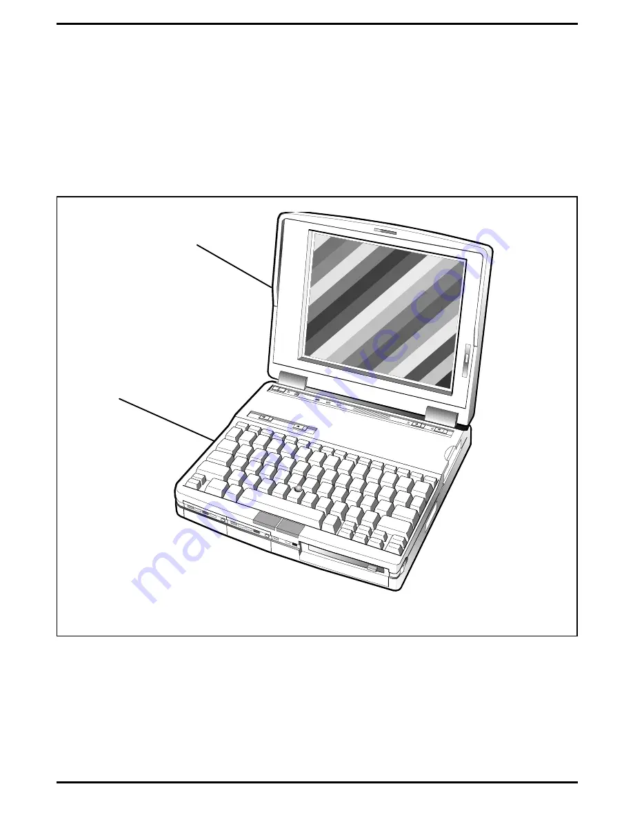
Mechanically, the Notebook Computer consists of two major assemblies
including the Cover-Display Assembly and the System Base Assembly as
shown in Figure 1-13.
Cover-Display
Assembly
System Base Assembly
Figure 1-13 Notebook Major Assemblies
1-26
General Description
Summary of Contents for TravelMate 5000 Series
Page 1: ...Maintenance Manual TravelMate 5000 Series Notebook Computers 9786166 0001 March 1995 ...
Page 47: ...Figure 1 16 TM5000 Series Functional Block Diagram 1 30 General Description ...
Page 95: ...Figure 4 2 Notebook Detailed Block Diagram Troubleshooting Procedures 4 3 ...
Page 149: ...Figure 6 4 Main Board P54 75MHz P N 9798803 0001 Sheet 2 of 2 6 14 Illustrated Parts Listing ...
Page 172: ...Figure 6 7 Keyscan Board P N 9786209 0001 Illustrated Parts Listing 6 37 ...
Page 180: ...Figure 6 11 Inverter Board P N 9786134 0001 Illustrated Parts Listing 6 45 ...
Page 185: ...Figure 6 12 DAB Board P N 9786273 0001 6 50 Illustrated Parts Listing ...
Page 228: ...Figure 7 5 Figure 7 5 IR Board P N 9798813 Logic Diagram Sheet 1 of 2 7 42 Schematic Diagrams ...
Page 229: ...Figure 7 5 Figure 7 5 IR Board P N 9798813 Logic Diagram Sheet 2 of 2 Schematic Diagrams 7 43 ...
Page 239: ...Figure A 1 Code Page 437 United States A 2 Character Sets ...
Page 240: ...Figure A 2 Code Page 850 Multilingual Character Sets A 3 ...
Page 241: ...Figure A 3 Code Page 863 Canadian French A 4 Character Sets ...
Page 242: ...Figure A 4 Code Page 865 Nordic Character Sets A 5 ...
Page 286: ...Printed in U S A ...


