Software Control
9
SLAU374B – December 2011 – Revised May 2016
Copyright © 2011–2016, Texas Instruments Incorporated
TSW308x Evaluation Module
•
FIFO Sync Select (DAC34H84 and DAC34SH84): Select the internal digital routing of LVDS ISTR or
LVDS SYNC to the FIFO ISTR path
•
FIFO Input Sync: Synchronization source for FIFO input pointer. Select among the LVDS FRAME
(ISTR), LVDS SYNC, and/or SPI register SIF-SYNC to reset the FIFO input pointer position.
•
FIFO Output Sync: Synchronization source for FIFO output pointer. Select among the LVDS FRAME
(ISTR), LVDS SYNC, SPI register SIF-SYNC, and/or OSTR signal to reset the FIFO output pointer
position.
–
For single device application without the need for precise latency control, Single Sync Source Mode
may be used. The FIFO output pointer position can be reset with LVDS FRAME (ISTR), LVDS
SYNC, and/or SPI register SIF-SYNC. See the Single Sync Source Mode in the relevant DAC348x
data sheet for details.
–
For multiple device synchronization, select the OSTR signal as the FIFO output synchronization
source. If the DAC is configured to accept external DAC Clock input, then the OSTR signal is the
external LVPECL signal to the OSTRP/N pins. If the DAC is configured to accept the internal on-
chip PLL clock, then the OSTR signal is the internally generated PFD frequency. See the Dual
Sync Sources Mode in the relevant DAC348x data sheet for details.
2.2.1.2
LVDS Delay Settings
Depending on the signal source implementation (that is, TSW1400, TSW3100, or FGPA system), the
following options can be implemented to meet the minimum setup and hold time of DAC348x data
latching:
•
Set the on-chip LVDS DATACLK delay: The DAC348x includes on-chip LVDS DATA or DATACLK
delay. The delay ranges from 0 ps to 280 ps with an approximate 40-ps step. This LVDS DATACLK
delay does not account for additional PCB trace-to-trace delay variation, only the internal DATACLK
delay. The TSW1400 and TSW3100 pattern generators send out LVDS DATA and DATACLK as edge-
aligned signal. Typical setting of 160 ps or more help meet the timing requirement for most of the
pattern generator and DAC348x EVM setup.
•
Modify the external LVDS DATACLK PCB trace delay: Additional trace length can be added to the
DATACLK P&N PCB trace length.
–
At the top side of the TSW3084, set SJP9, SJP10, SJP11, and SJP12 to the 2-3 position for
approximately 2 inches (320 ps) of trace delay.
–
At the top side of the TSW3085, set SJP1, SJP6, SJP7, and SJP8 to the 2-3 position for
approximately 2 inches (320 ps) of trace delay.
–
At the top side of the TSW30H84, set SJP9, SJP10, SJP11, and SJP12 to the 2-3 position for
approximately 1 inches (160 ps) of trace delay.
2.2.1.3
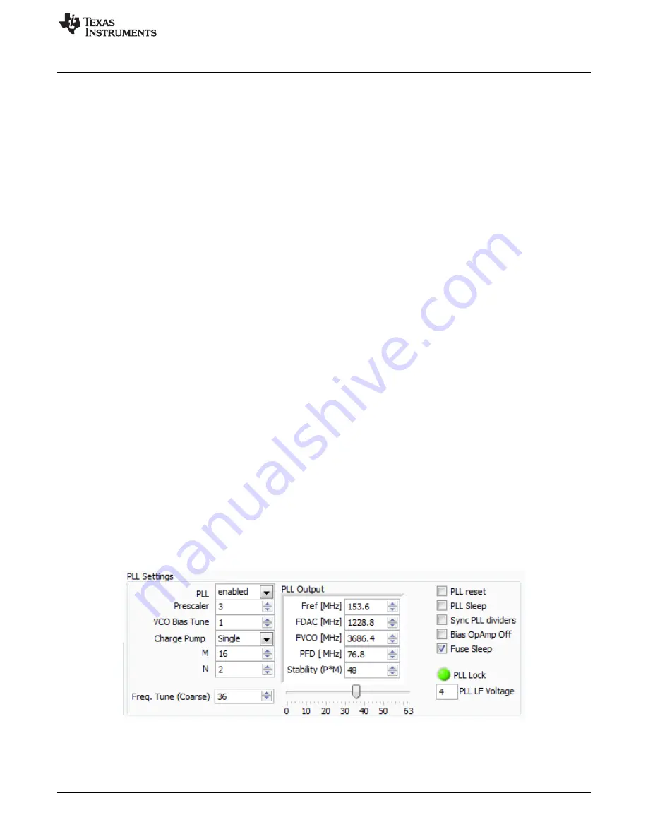
PLL Settings
Figure 5. PLL Configuration


