www.ti.com
5.2
PC Control Mode
5.3
Direct Control Mode
6
VCA8500BOARD Full-Access Software
6.1
Loading the Software
6.2
Initial Start-up Screen
VCA8500BOARD Full-Access Software
This mode requires P10 to be shorted using surface-mount jumpers. This allows the VCA to interface with
the microcontroller. Switch S1 is not installed, and the settings are hard-wired to PC-Control mode. The
VCA8500 is controlled by the software running on a PC. At this point, the serial cable included with the
VCA8500BOARD must be connected to the PC serial port. The program called VCA8500EVM then sets
the proper baud rate for communication with the VCA8500BOARD. By using a PC to control the
VCA8500, the entire device functionality is available for testing. The software provides the ability to select
any of the clamp ranges and PGA gains settings, direct an input to any CW output, or power down the
complete chip.
Remove solder jumpers from P10, and connect the external source to DIN, CLK, DOUT, and CS. These
are SMA connectors J30, J31, J32, and J33, respectively. This allows for direct control of the VCA8500
with an external control source such as a digital word generator.
The CD-ROM includes full-access installation software, data sheet, and EVM schematic
Insert the CD-ROM into the PC. Select the folder called
Installation Software
, and double-click on
Setup.exe. The installation wizard guides you through the rest of the installation process.
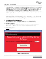
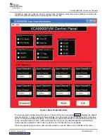
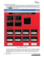
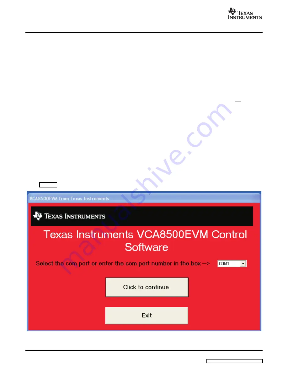
shows the initial start-up screen.
Figure 2. Initial Start-up Screen
4
VCA8500BOARD
SLOU216 – January 2008


