Design Files and Software Tools
16
SPRUIM4B – December 2018 – Revised May 2020
Copyright © 2018–2020, Texas Instruments Incorporated
xWR1843 Evaluation Module (xWR1843BOOST) Single-Chip mmWave
Sensing Solution
3
Design Files and Software Tools
3.1
Hardware
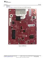
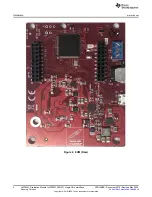
To view the schematics, assembly drawings, and BOM, see
AWR1843BOOST Schematic, Assembly
To view the design database and layout details, see
NOTE:
Boards with a Rev 'D' sticker have had capacitor C56 (VBGAP decoupling capacitor)
changed from 0.22 µF to 0.047 µF (part number CGA2B3X7R1H473K050BB). TI
recommends that customers incorporate this change with an equivalent capacitor in their
designs.
3.2
Software, Development Tools, and Example Code
To enable quick development of end applications on the C67x DSP and R4F core in the xWR1843, TI
provides a software development kit (SDK) that includes demo codes, software drivers, emulation
packages for debug, and more. These can be found at
3.2.1
LDO Bypass Requirement
The xWR1843BOOST utilizes a 1.0-V supply on the RF1 and RF2 power rails. To support the third
transmitter, the VOUT_PA output is connected to the RF2 power rail. For best performance and to prevent
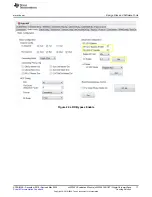
damage to the device, select the 'RF LDO Bypass Enable' and 'PA LDO I/P Disable' options in the Static
Configuration when using mmWave Studio. Additionally, the LDO bypass can be configured using the
AWR_RF_LDO_BYPASS_SB API. To enable the RF LDO Bypass and PA LDO I/P Disable through the
API, issue an ar1.RfLdoBypassConfig(0x3) command.


