13
Identification of parts
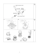
See fig.1 illustration:
Assembly
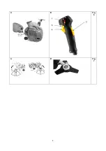
Follow the mounting procedure as shown in Fig.2-
A, Fig 2-B and Fig 3
1. Mount the protection guard. See Fig.2-A
2. Attach the middle tube to the machine, fasten
with butterfly knob. See Fig 2-B
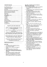
3. Mount the throttle lever and handle as shown
in Fig 3 illustration A. Ensure that the machine
is in balance and bolt are tighten.
Use Brush cutter and Grass trimmer
•
When the engine is stopped the rotating blade
must be held in grass or bush until it holds
still.
•
Always hold the machine with both hands.
•
The machine must not be used if the safety
guard is not correctly fitted and in mint
condition.
•
Always stop the engine before attempting to
remove objects that may have stuck on the
blade.
•
Never touch or try to stop the blade while it is
still spinning.
•
A rotating blade may cause damage, as it
continues to spin after the engine has stopped
or the gas has been turned off. Always be in
control of the tool until the blade has stopped
spinning.
•
Always make sure that the blade is mounted
securely and correctly before every time is
used.
•
Only use a sharp blade. Replace blades that
are worn or damaged.
•
Only use original spare parts.
•
Only use the blade for weeds, grass and
similar.
•
Throw back is something that may occur
when the rotating blade gets into contact with
something, it cannot cut. This contact may
have the effect, which the blade stops for a
moment, and suddenly the tool is thrown
away from the hard object that was hit. This
reaction may be so violent that the user loses
control of the tool. Throw back may occur
without warning if the blade is stuck, loses
speed or impeded. This is most likely in areas
where it is difficult to see the material that is
being cut.
•
The harness must always be used and
adjusted to fit in the correct manner.
•
Keep a firm grip on both handles while the
blade is running. Keep the blade away from
your body and below your waist.
Changing from trimmer to brush cutter
Dismounting the trimmer head
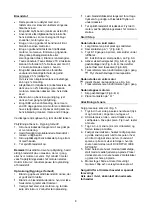
See Fig 4B
1. Fit the Allen key (2) in the hole of the gear (3)
to lock the gear in place.
2. Turn and remove the trimmer head (1) from
the shaft.
3. Washers can now be removed
Notice:
Keep the parts for the trimmer head
together for later use.
Mounting of blade.
See Fig 4A
1. Fit the Allen key (2) in the hole of the gear (3)
to lock the gear in place.
2. Fit the washer (7), blade (1), washer (6) and
the holder (5) onto the axle.
3. Fit the nut (4). Fasten tightly anticlockwise.
Make sure the blade is securely fasten.
Insure that the blade is tightly fastened
Changing from brush cutter to trimmer
Dismounting the blade
See Fig 4A
Follow the procedure as shown in Fig.4-A
1. Fit the Allen key (2) in the hole of the gear (3)
to lock the gear in place.
2. Loosen and remove the nut (4) that fastens
the blade.
3. Washers, holder and blade can now be
removed.
Notice:
Keep the parts for the blade together for
later use.
Mounting of trimmer head.
See Fig 4B
Follow the procedure as shown in Fig.4-B
1. Fit the Allen key (2) in the hole of the gear (3)
to lock the gear in place.
2. Fit the washers (4+6)
3. Mount the trimmer head (1) onto the shaft,
turn it in place and make sure it is securely
fasten.
A Engine
C Bracket
E
Cutter –
Trimmer
B
Throttle
lever –
Handle
D Guard F
Tube with
lock knob


