12
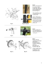
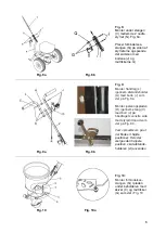
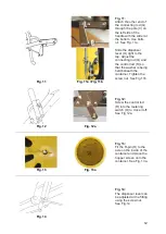
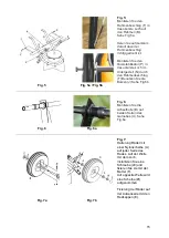
Fig. 11:
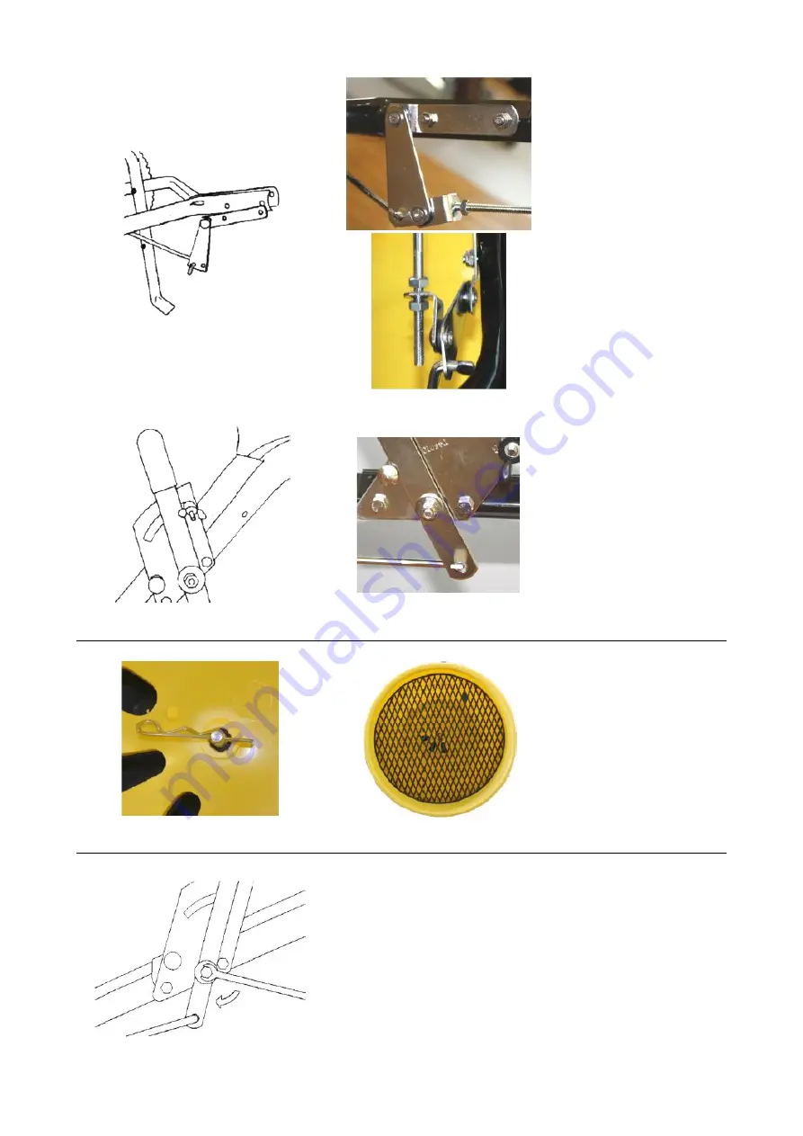
Attach the other end of
the connecting rod (Q)
through the pole (V) on
the left side of the
handle with the slider at
the bottom. Use bolts
(J). See Fig. 11a.
Slide the dispenser
lever (O) right to the
top. Adjust the
connecting rod (Q) and
the control rod (R) so
that the washer is being
held beneath the
container. Tighten the
screw nut. See Fig.11b.
Fig. 11
Fig. 11a / Fig. 11b
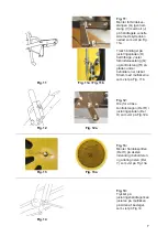
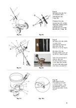
Fig. 12:
Screw the control rod
(R) into the metering
switch (O) to close it off.
See Fig 12a.
Fig. 12
Fig. 12a
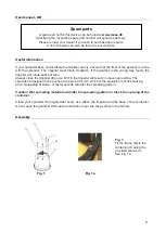
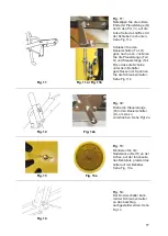
Fig. 13:
Fit the R-pin (H) to the
axle on the inside of the
container and place the
hopper screen onto the
container. See Fig. 13a.
Fig. 13
Fig. 13a
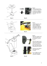
Fig. 14:
The dispenser lever can
be adjusted at the fitting
using the screw nut.
See Fig.14
Fig. 14


