Input Configuration
1-5
General Information
1.3
Input Configuration
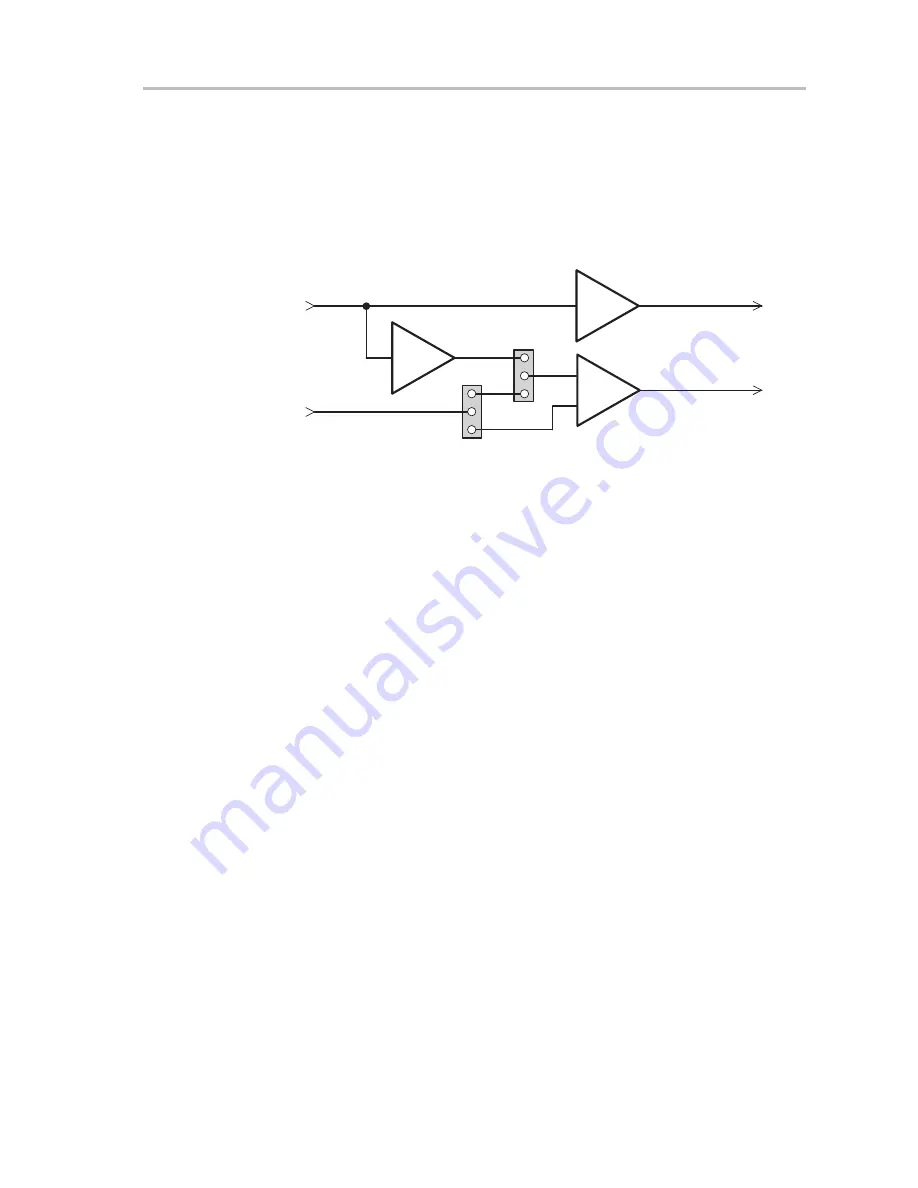
The THS6022 EVM inputs can be configured in several different ways to
provide a wide variety of circuits to support different applications
(Figure 1–3). Each of the two jumpers on the EVM is a three-pin header that
is used as a SPDT switch by placing a shunt across two pins to select either
of two possible signal routes.
Figure 1–3. THS6022 Evaluation Module Block Diagram
J4
1
3
2
JP1
1
3
2
JP2
–
+
J6
THS6022
THS6022
THS4001
U1
U2: A
U2: B
Driver 1 Output
Driver 2 Output
Driver 1
Input
Driver 2
Input
Positive Driver
Inverter
Negative Driver
J5
J7
-
Jumper JP1:
J
1–2 — connects the noninverting input of driver 2 (U2: B) to the
THS4001 inverting amplifier (U1) output
J
2–3 — connects the noninverting input of driver 2 (U2: B) to the input
connector (J6) when jumper JP2 is set appropriately
-
Jumper JP2:
J
1–2 — connects the driver 2 input connector (J6) to the noninverting
input of driver 2 (U2:B) when jumper JP1 is set appropriately
J
2–3 — connects the driver 2 input connector (J6) to the inverting input
of driver 2 (U2:B) when jumper JP1 is set appropriately
For example, to use a single-ended input, jumper JP1 should be set to 1–2 and
the input signal applied to input connector J4. The output of the THS6022
drivers is a differential signal due to the inverter (U1) and JP1 being set to 1–2.
For a differential source, JP1 should be set to 2–3, JP2 should be set to 1–2
and the differential input signal applied between input connectors J4 and J6.
If JP2 is in the 2–3 position, components C12 and R11 must be installed, R9
must be removed, and a 0-
Ω
resistor must be installed in the C11 position for
proper operation.
1.4
THS6022 EVM Specifications
Supply voltage range,
±
V
CC
±
5 V to
±
15 V
. . . . . . . . . . . . . . . . . . . . . . . . . . . . . . . . . . . . . . . . . . . .
Supply current, I
CC
23 mA
. . . . . . . . . . . . . . . . . . . . . . . . . . . . . . . . . . . . . . . . . . . . . . . . . . . . . . . . . . .
Input voltage, V
I
±
V
CC
, max
. . . . . . . . . . . . . . . . . . . . . . . . . . . . . . . . . . . . . . . . . . . . . . . . . . . . . . . . .
Output drive, THS6022 Drivers, I
O
250 mA, typ each
. . . . . . . . . . . . . . . . . . . . . . . . . . . . . . . . . . . .
Continuous total power dissipation at TA = 25
°
C (THS6022),
3.3 W, max
. . . . . . . . . . . . . . . . . . .
For complete THS6022 amplifier IC specifications and parameter
measurement information, and additional application information, see the
THS6022 data sheet, TI Literature Number SLOS225.
Summary of Contents for ths6022
Page 4: ...iv ...
Page 18: ...1 12 General Information ...


