background image


Premier Elite Ricochet Kits Quick Guide 

INS626 

Introduction 

Texecom has developed a new method of wireless security signalling based on the concept of mesh networking. Mesh-networking 
is the process whereby every single wireless device is capable of receiving and retransmitting any signal from any other wireless 
device on the network. The size, scalability and range of the entire system are extended as wireless signalling is no longer limited 
by point-to point communications.  The range of a 

Ricochet

®

  enabled wireless system is  greater than previous systems, with 

multiple devices capable of relaying messages to and from even the most remote locations in a building. Each 

Ricochet

 enabled 

device provides signalling routes to and from Premier control panels. If the wireless communication between devices weakens, the 

Ricochet

 network ‘self-heals’ and automatically re-routes communications via alternate 

Ricochet

 enabled devices. The reliability of 

the wireless system increases as more 

Ricochet

 devices are installed. 

SignalSecurity™ further enhances network reliability with 

each device already aware of the number of communication paths available to it. 

This quick start guide will enable you to install and programme the system. Detailed instruction manuals for all of the components 

of the kits can be found on the enclosed CD. Any additional items purchased will also contain detailed instructions. 

Additional Items Required 

In addition to the contents of the kit you will need the following to complete the installation:- 


7Ah Lead Acid back up battery 


Alarm cable (if installing remote keypads or wired detection devices & sounders) 


Mains Cable 


3A unswitched fused spur 


Screws & Rawl plugs (No6, No8 & No10) 


Hammer drill, various screwdrivers 


Mini Trunking. 


PC or Laptop running Windows Vista, 7 or 8 (If programming from a PC) 


JAC-0001 Texecom USB Com Lead (If programming from a PC) 


A cover for the External Sounder 

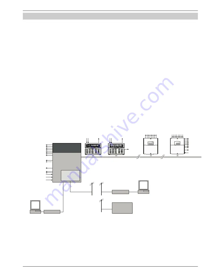
System Architecture 

3 or 8 Progra mmable

 100mA Outputs

Bell Ta mper  Input

4 Zones

1 or 2 Programmable  

A )

Outputs

(2 x 500m

Pre mier Elite

12/24/48-W

Pre mier LC D/LC DP

Pre mie r LC DL /LC DLP

Pre mier E lite  LC DL P

4 Wire Data Network 1

16 Programmable

100mA Outputs

2  ( 12 -W ) or 4 ( 24-W /48-W ) K e ypa ds

Premier  Elite OP 16

1 (24 -W )   or  2 (48 -W )  

O utput M odule s

Alarm R eceiving

Centre

Modem

PC  and Modem for 

R emote Upload/Download

P C/USB -C om

PC  and 

 for

Local Uploa d/Download

PC/US B-C om

Plug on Digimode m


Plug on

(C om300 or C om2400)

 Ra dio-Pa d,

GS M Module

2 Zone

Inputs

1Programmable

100mA Output

2 Zone

Inputs

1Programmable

100mA Output

S pea ker

Output

S pe aker Output

8 Zone Inputs

Auxiliary Input

Premie r Elite 8XP

8 Programmable

 100mA Outputs

2(2 4-W)  or 3(4 8-W)  only 

E xpanders

4 to 4 8 Zones

8 -32  W ireles s  Device  s lots

Be ll/S trobe Outputs

8 or 32 De vice  

Wi rele ss  R ec eiv er

S pe aker Output

Auxiliary Ta mper  Input


Summary of Contents for INS626 Premier Elite Ricochet Kits

Page 1: ...Manual De Usuario Premier 412 816 832 Issue 2 Quick Start Guide Premier Elite Ricochet Enabled Kits INS626...

Page 2: ...onnecting Keypads Expanders 7 Premier Elite 12 24 48 W Live Front 7 Wiring the Network 7 Keypad Expander Addressing 8 Installing Ricochet devices 8 Learning Devices 8 Device Type 8 Learn method 8 Auto...

Page 3: ...e found on the enclosed CD Any additional items purchased will also contain detailed instructions Additional Items Required In addition to the contents of the kit you will need the following to comple...

Page 4: ...EABLE PARTS NO USER ACCESS ONLY connect the mains supply to the mains terminal block NEVER connect the mains supply directly to the PCB ALWAYS refer to National Wiring Regulations when conducting inst...

Page 5: ...and maintenance System Keypads Should be placed on the entry route if used for arming and disarming Should be placed with the Control Panel if SmartKeys or the App s are used for arming disarming Move...

Page 6: ...rs code 1234 again i Connect AC Mains 3 The Keypad display will now show Confirm Devices press and again to confirm that all connected keypads and expanders are accounted for 4 The Keypad display will...

Page 7: ...each network The maximum number of devices that can be connected in total will depend on the control panel fitted Whenever new devices are connected to the networks they must be confirmed onto the sy...

Page 8: ...ll ensure that they are registered on the receiver or control panel and that Mesh Networks and routing are established correctly SmartKey should be learned after all other devices have been assigned t...

Page 9: ...stem Use the or to select different zones It is only possible to select Zones which have devices learned The key will cycle between the Learn or Delete options If all devices are deleted from the syst...

Page 10: ...the LE D Aux functions Using the key at this point allows you to view the group of zones and therefore the expander that the S martKey will use Use the key to select the group of Zones and Expander yo...

Page 11: ...ite Installation Manual which is on the enclosed CD or available to download from our website Default Engineer Code 00 1234 Default User Code 01 5678 Log Off Engineer Press to log out of the Engineer...

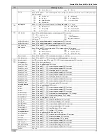
Page 12: ...for Areas 3 Entry Dly 2 for Areas 8 Part Bell Dly for Areas 4 2nd Entry Dly for Areas 9 Conf PA Timer for Areas 5 Bell Dly for Areas Arming Modes Use to select an area to select arming an mode to acc...

Page 13: ...33 Poll IP Every 10 Menu Time Out 22 Max Random Time 11 Pulse Period 1 23 Door Strike Time System Config Use to select an option to change the option to accept 00 No Bell Bell on Arm Fail 19 Auto Man...

Page 14: ...4 48 88 168 Use to select keypad to select network to edit to select an area all areas areas A H and I P to accept Areas 640 Use to select keypad to select network to edit to select an area group 1 4...

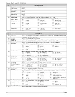
Page 15: ...Bell Tamper 22 Custom 1 Stage A 39 Com 2 Fault 05 Panel Lid Tamper 23 Custom 1 Stage B 40 Com 1 No Signal 06 Engineer Working 24 Custom 1 Stage AB 41 Com 2 No Signal 07 Confirm Devices 25 Custom 2 Sta...

Page 16: ...tor Start Test call Press to send test call to the ARC to initiate a call to the remote UDL computer using Call Back numbers 1 2 or 3 Msn Pre Dial Number Press to edit enter call waiting number to acc...

Page 17: ...Press to edit to enter pad prefix to accept Pad ARC 2 Pri No Press to edit to enter telephone number to accept Pad ARC 2 Sec No Press to edit to enter telephone number to accept Pad ARC 2 Prefix Press...

Page 18: ...neer Standard Door Strike Local Vacation User Options 1 Press to edit to select an option to change option to accept A Arming R Eng Reset Y Auto YES D Disarming a Local Arming D Disarm First O Omittin...

Page 19: ...ount Check RKP Status Use to select keypad to select network to display errors tamper to test output to test sounder Check Exp Status Use to select expander to select network to display zones voltage...

Page 20: ...ry default Master User code is The Master User is always User 01 If the Master User code has been lost or forgotten it can be reprogrammed by the Engineer in this menu Changing the Default Codes To ch...

Page 21: ...12 W 24 W 48 W 4 Onboard Zones Max 8 16 or 32 wireless device Ricochet enabled receiver onboard Expandable to 12 48 zones via keypads and zone expanders 1 x 4 wire data network standard 7 0 2 alarm ca...

Page 22: ...The red LED indicates that data is flowing out of the control panel and normally flashes very quickly The green LED indicates that data is flowing into the control panel and normally flashes slowly th...

Page 23: ...es to all ON 20 Ricochet Firmware Flash Port Connections for flasher interface to update Ricochet receiver firmware factory function only 21 Commission Mode Jumper Fit when learning and placing device...

Page 24: ...4 4PW England Technical Support UK Customers Tel 08456 300 600 Calls charged at local rate from a BT landline Calls from other networks may vary International Customers Tel 44 1706 233875 Email techsu...

Reviews: