Premier Elite PSU200 & PSU200XP Installation Manual
3
INS314-3
PCB Layout and Terminals
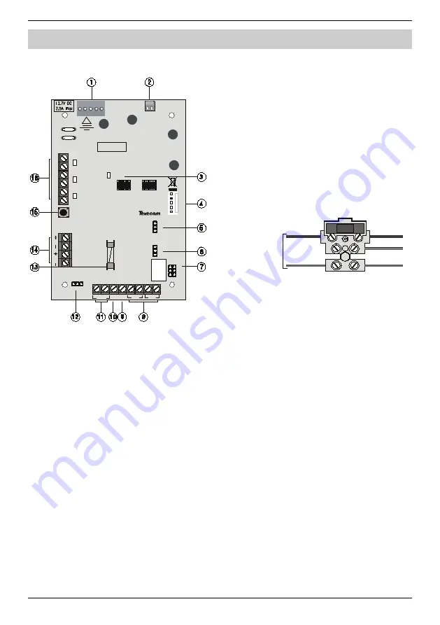
The figure below shows the PCB layout of the
PSU200
and
PSU200XP
:
2 J P 8 1
K ick
S ta rt
F 1
J P 2
Co
m
1
A.C
F
ail
Ba
tt F
lt
O
/P
F
lt
B1
B2
B a tter ie s
Tamp
L ed L oa d
0V
12V
J
P7
0.
7
5A
/0.
3
A
J
P6
0.
7
5A
/0.
3
A
J P 9
A
B
C
L oa d
A = E x t Loa d
B = 5 0 0m A
C = 50 0 mA
P owe r
!
B AR C ODE
Figure 2. PCB Layout
1.
Texecom
Power Supply Connection.
2.
Connector to case tamper switch.
3.
Power LED
4.
Communication port (for connection to
8XP
zone expander).
5.
Battery 1 charge current selector (0.75A or
0.30A).
6.
Battery 2 charge current selector (0.75A or
0.30A).
7.
Battery load test options.
8.
12V supply output.
9.
External load for battery load test.
10.
Not Used
11.
Normally closed tamper output.
12.
Number of batteries connected.
13.
12V output protection fuse (1.6A).
14.
Battery 1 and 2 connections.
15.
Battery kick start switch.
16.
Normally closed fault outputs and status led’s.
Mains Supply Connection
The mains supply is connected to a 3 way fused terminal
block, which is fitted with a 3.15A slow blow protection fuse.
The supply cabling should also incorporate an accessible
double pole disconnect device so that the supply can be
isolated.
All electrical connections should be carried
out by a qualified electrician.
After connecting the mains supply, fit the
mains protection cover to the fused terminal
block, this can be found in the spares bag.
Secure the mains cable to the anchor point
using a cable tie.
L
E
N
To Power S upply
Mains Fuse
Supply Output
Two sets of terminals are provided to allow connection to
auxiliary 12V devices. The output is protected by a 1.6A fuse.
Tamper Protection
The power supply is both front and back tamper protected
by the use of a tamper switch which is connected to the PCB
via a jumper plug JP2. When installing a
PSU200
the two
tamper connections terminals should be connected to the
tamper or 24hour zone of the alarm control panel. The
tamper connections are not required for the
PSU200XP
as
the tamper status is detected through the communication
port.
Fault Outputs and Indicators
Individual outputs and indicators are provided for the
following faults:
A.C Fail: A normally closed set of contacts which open when
the mains supply to the unit fails. The associated red status
led also lights when this fault is present.
Battery Fault: A normally closed set of contacts which open
when a battery fault is detected. The associated red status
led also lights when this fault is present.
Output Fault: A normally closed set of contacts which open
when the output fuse (F1) fails or output voltage falls below
11V. The associated red status led also lights when this fault
is present.
When installing a
PSU200
the fault outputs terminals should
be connected to individual zones or auxiliary inputs of the
alarm control panel. The fault outputs are not required for the
PSU200XP
as the fault status is detected through the
communication port.


