Premier Elite PSU200 & PSU200XP Installation Manual
5
INS314-3
Installation
1.
Remove the screw from the front cover and carefully
slide it upwards to disengage the cover from the bottom
clip.
2.
Gently pull the cover towards you noting that earth is
connected to a spade terminal on the front cover.
3.
Unplug the earth lead from the spade connection on the
inside of the front cover. The front cover can now be fully
removed and placed to one side.
4.
Position the base in the required location and mark at
least four of the available mounting holes. If the back
tamper is required the keyhole must also be marked.
5.
Remove the base and drill and plug the holes.
6.
Pass all necessary cables through the cable entries and
fix the base to the wall using not less than 30mm x No 10
screws.
7.
Connect the mains cable to the fused mains terminal
block.
8.
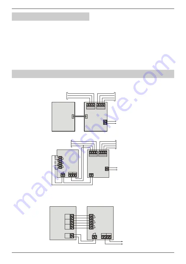
Connect the terminals on the PCB as required, see
Wiring Diagrams.
9.
Fit the appropriate standby battery or batteries and
connect the battery leads to the battery terminals.
10.
Apply mains power and check the operation of the power
supply.
11.
Refit the front cover, remembering to connect the earth
lead to the front cover.
12.
Replace the front cover screw.
Wiring Diagrams
PSU200XP
Connected to
Premier Elite
Control Panel
For a list of supported control panels, see page 2.
8XP
+
-
A ux 12 V
PSU200
To Next E xpander/Keypad
To 12V Devices
From Control Panel
+
T
R
-
Ne twork In
+
T
R
-
Ne twork Out
PS U
Com1
PSU200 Connected to an 8XP
8XP
+
-
A ux 12 V
PSU200
To Next E xpander/Keypad
To 12V Devices
From Control Panel
A
C F
ail
B
att
F
lt
O
/P
F
lt
Tam p
0 V
12 V
Aux I/P
+
T
R
-
Ne twork In
+
T
R
-
Ne twork Out
2K 2
4K 7
10K
Program Aux I/P as “PSU Monitor”.
PSU200
Connected to a non
Premier
Control Panel
The
PSU200
can be fully monitored by other makes of control panels, by using the fault and tamper terminals. The zones on the control
panel will need to be programmed for PSU monitoring functionality. Please consult the manufacturer’s instructions in order to ascertain
whether the control panel supports these zone types.
PSU200
To 12V Devices
A
C F
ail
B
att
F
lt
O
/P
F
lt
Tam p
0 V
12 V
Non
Control Panel
Premier
Zone x
Zone y
Zone z
Tam per


