106
5.
Press
Main
>
Configure [F5]
>
Next Menu [F4]
>
External [F3]
.
6.
Set the
Control
parameter to V.
The J1 connector is now ready for
external voltage control.
7.
Reset the power to apply the settings.
The unit is now ready for external voltage control.
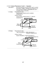
4-1-4. External Resistance Control - Overview
Background
External resistance control of the CC, CR, CV
and CP modes is accomplished using the J1
connector on the rear panel.
A resistance of 0kΩ~10kΩ is used to control the
input current, voltage, resistance or power on the
LSG Series.
The input can be configured to vary in proportion
to the external resistance or the inverse. See
page 107 for more details on proportional and
inverse resistance control.
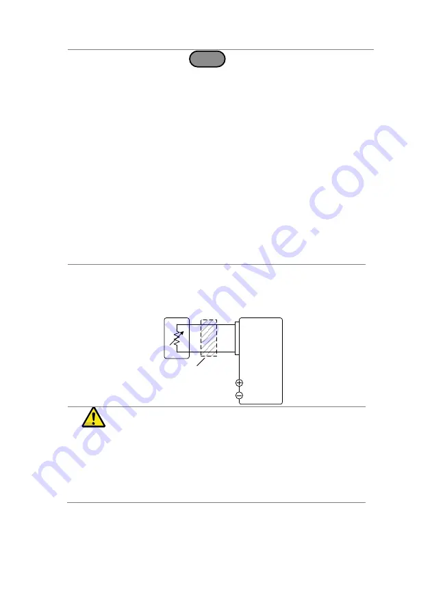
Connection
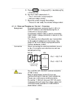
When connecting the external resistance source
to the J1 connector, use a ferrite core and use
twisted pair wiring.
LSG
EXT-R
J1
connector
3
1
Input
Terminals
Ferrite Core and
twisted wiring
Pin1 → EXT
-R
Pin3 → EXT
-R
Note
Use resistors with minimum residual resistance
of 50Ω or less.
Note for proportional control: Do not use
swtiches that switch between fixed resistances.
Please use continuously variable resistors.
Exceeding 11.8kΩ will cause an EXT.OV alarm
message which will reset the voltage output to 0
until the external resistance is reduced back
down
below 11.8kΩ.
Summary of Contents for LSG SERIES
Page 8: ......
Page 23: ...11 GRA 414 E EIA standard 132 382 5 477 6 GRA 414 J JIS standard 149 382 5 477 6 ...
Page 149: ...137 7 6 Operating Area LSG 175 ...
Page 150: ...138 LSG 350 ...
Page 151: ...139 LSG 1050 ...
Page 166: ......

