111
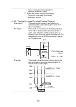
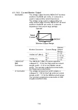
LSG
Switches
Analog
connector
12
+5V
A COM
8
9
10k
Ω
Note
The range can only be externally controlled
when the IRange has been set to High using the
front panel controls.
4-1-9. I Range Status
Description
Pins 14 and 15 (Range Status 1&0) of the J1
connector are used to monitor the IRange status.
The pin out combination determines the range
status.
I Range
Pin 14
Pin 15
H
Off
Off
M
Off
On
L
On
Off
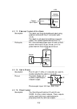
Pin out
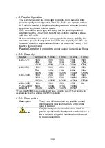
The Range Status
pins are photo-
coupled open-
collector outputs.
17
14, 15
Photocoupler input: 30V max, 8mA, max.
4-1-10. External Trigger Signal
Description
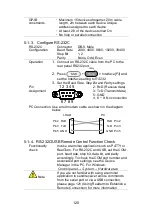
Pins 11 and 12 of the J1 connector are the
trigger signal inputs. The trigger signal is used to
resume a sequence after a pause. This action is
useful to synchronize the execution of a
sequence with another device.
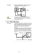
Pin out
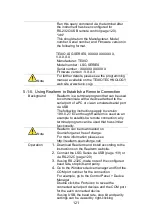
Pin 11 of the J1 connector is internally pulled
down to A COM with a 100k
Ω resistor. To use
the trigger input, an active low TTL pulse of 10μs
or more is required.
Summary of Contents for LSG SERIES
Page 8: ......
Page 23: ...11 GRA 414 E EIA standard 132 382 5 477 6 GRA 414 J JIS standard 149 382 5 477 6 ...
Page 149: ...137 7 6 Operating Area LSG 175 ...
Page 150: ...138 LSG 350 ...
Page 151: ...139 LSG 1050 ...
Page 166: ......


