150
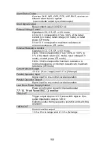
Alarm Status Output
On when OVP, OCP, OPP, OTP, UVP, RVP, or when an
external alarm input is applied
(open collector output by a photocoupler)
Short Signal Output
Relay contact output (30 VDC/1 A)
External Voltage Control
Operates in CC, CR, CP, or CV mode
0 V to 10 V correspond to 0 % to 100 % of the rated
current (CC mode), rated voltage (CV mode), or rated
power (CP mode).
0 V to 10 V correspond to maximum resistance to
minimum resistance (CR mode)
External Resistance Control
Operates in CC, CR, CP, or CV mode
0 Ω to 10 kΩ correspond to 0 % to 100 % or 100 % to
0 % of the rated current (CC mode), rated voltage (CV
mode), or rated power (CP mode).
0 Ω to 10 kΩ correspond to maximum resistance to
minimum resistance or minimum resistance to maximum
resistance (CR mode)
Current Monitor Output
10 V f.s. (H or L range) and 1 V f.s. (M range)
Parallel Operation Input
Signal input for one-control parallel operation
Parallel Operation Output
Signal input for one-control parallel operation
Load Boost Power Supply Control
Power on/off control signal for the load booster
7-7-16. Front Panel BNC Connector
TRIG OUT
Trigger output: Approx. 4.5 V pulse width: Approx. 2 μs,
output impedance: Approx. 500 Ω
Outputs a pulse during sequence operation and switching
operation.
I MON OUT
Current monitor output
1 V f.s. (H or L range) and 0.1 V f.s. (M range)
Summary of Contents for LSG SERIES
Page 8: ......
Page 23: ...11 GRA 414 E EIA standard 132 382 5 477 6 GRA 414 J JIS standard 149 382 5 477 6 ...
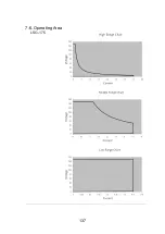
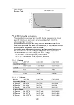
Page 149: ...137 7 6 Operating Area LSG 175 ...
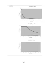
Page 150: ...138 LSG 350 ...
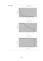
Page 151: ...139 LSG 1050 ...
Page 166: ......

