48
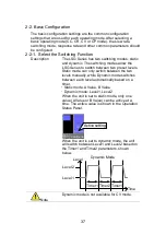
Display
Parallel
Knob
External
Previous
Menu
CRH Step
0.4
CCL Step
0. 183575
LOAD
RS232
31/Oct/2013
Step
mS
A
CCM Step
CCH Step
0. 5000
1. 000
A
A
CC
35A
15V
Static
Configure
Status
2-5. Protection Settings
The Protection settings are used to prevent damage to the unit or the
DUT by excessive current, voltage or power.
An alarm is generated and a message is displayed on the screen
when a protection setting is tripped. When an alarm is activated, the
load is turned off (or limited), and the ALARM STATUS pin of the J1
connector on the rear panel (pin 16) turns on (open collector output
by a photocoupler). The protection settings can be used regardless of
whether the remote sense connections are used or not.
2-5-1. OCP
Description
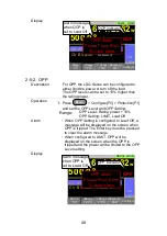
For OCP, the LSG Series can be configured to
either limit the current or turn off the load.
The OCP levels can be set to 10% higher than
the rating current.
Operation
1.
Press
Main
>
Configure[F5]
>
Protection[F1]
and set the
OCP Level
and
OCP Setting
.
Range:
OCP Level: Rating c 10%
OCP Setting: LIMIT, Load Off
Alarm
When
OCP Setting
is configured to
Load Off
, a
message will be displayed on the screen when
OCP is tripped. The Enter key must be pressed
to clear the alarm message.
When configured to
LIMIT
, OCP will be
displayed on the screen when the OCP is
tripped and the current will be limited to the
OCP Level
setting.
Summary of Contents for LSG SERIES
Page 8: ......
Page 23: ...11 GRA 414 E EIA standard 132 382 5 477 6 GRA 414 J JIS standard 149 382 5 477 6 ...
Page 149: ...137 7 6 Operating Area LSG 175 ...
Page 150: ...138 LSG 350 ...
Page 151: ...139 LSG 1050 ...
Page 166: ......

