112
LSG
Trigger
input signal
Analog
connector
12
11
A COM
50k
Ω
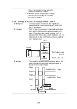
4-1-11. External Control of the Alarm
Description
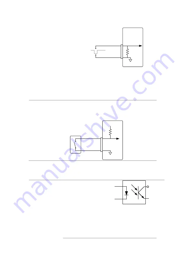
The alarm can be activated/deactivated using
external control with the J1 connector (pins
10,12).
The alarm is activated by sending a low-level
signal. The operating threshold level is TTL.
Pin Inputs
Pin 10 is internally pulled up to 5V with a 10kΩ
resistor when open. When closed, pin 10 is
pulled down to the A COM ground level.
LSG
Switch
Analog
connector
12
10
+5V
A COM
10k
Ω
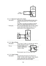
4-1-12. Alarm Status
Description
Pins 16 and 17 of the J1 connector are used to
monitor whether the alarm is on or off.
Pin out
The Alarm Status pin is
a photo-coupled open-
collector output.
17
16
Photocoupler input: 30V max, 8mA, max.
4-1-13. Short Control
Description
The Short Signal Out pins (19 and 20) are
30VDC 1A relay contact outputs. These outputs
can be used to drive an external relay to
physically short the terminal outputs.
Summary of Contents for LSG SERIES
Page 8: ......
Page 23: ...11 GRA 414 E EIA standard 132 382 5 477 6 GRA 414 J JIS standard 149 382 5 477 6 ...
Page 149: ...137 7 6 Operating Area LSG 175 ...
Page 150: ...138 LSG 350 ...
Page 151: ...139 LSG 1050 ...
Page 166: ......

