14
1-4-5. Load Wiring
Wire Gauge
considerations
Before connecting the unit to a power source,
the wire gauge must be taken into account.
Load wires must be large enough to resist
overheating when a short-circuit condition
occurs as well as to maintain a good regulation.
The size, polarity and length of a wire are all
factors in determining if a wire will withstand
short circuiting.
Wires that are selected must be large enough to
withstand a short circuit and limit voltage drops
to no more than 2V per wire. Use the table
below to help make a suitable selection.
AWG
Gauge
Conduct or
Diameter
mm
Ohms per
km
Max amps for
chassis wiring
0000
11.684
0.16072
380
000
10.4038
0.2027
328
00
9.26592
0.25551
283
0
8.25246
0.32242
245
1
7.34822
0.40639
211
2
6.54304
0.51266
181
3
5.82676
0.64616
158
4
5.18922
0.81508
135
5
4.62026
1.02762
118
6
4.1148
1.29593
101
7
3.66522
1.6341
89
8
3.2639
2.0605
73
9
2.90576
2.59809
64
10
2.58826
3.27639
55
11
2.30378
4.1328
47
12
2.05232
5.20864
41
13
1.8288
6.56984
35
14
1.62814
8.282
32
Load Line
Inductance
Considerations
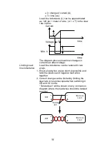
When using the LSG Series load generator,
voltage drop and voltage generated due to load
line inductance and current change must be
taken into account. Extreme changes in voltage
may exceed the minimum or maximum voltage
limits. Exceeding the maximum voltage limit
may damage the LSG Series.
To determine the voltage generated, the
following equation can be used.
E = L x (∆ I / ∆ T)
E= voltage generated
L=load line inductance
Summary of Contents for LSG SERIES
Page 8: ......
Page 23: ...11 GRA 414 E EIA standard 132 382 5 477 6 GRA 414 J JIS standard 149 382 5 477 6 ...
Page 149: ...137 7 6 Operating Area LSG 175 ...
Page 150: ...138 LSG 350 ...
Page 151: ...139 LSG 1050 ...
Page 166: ......

