20
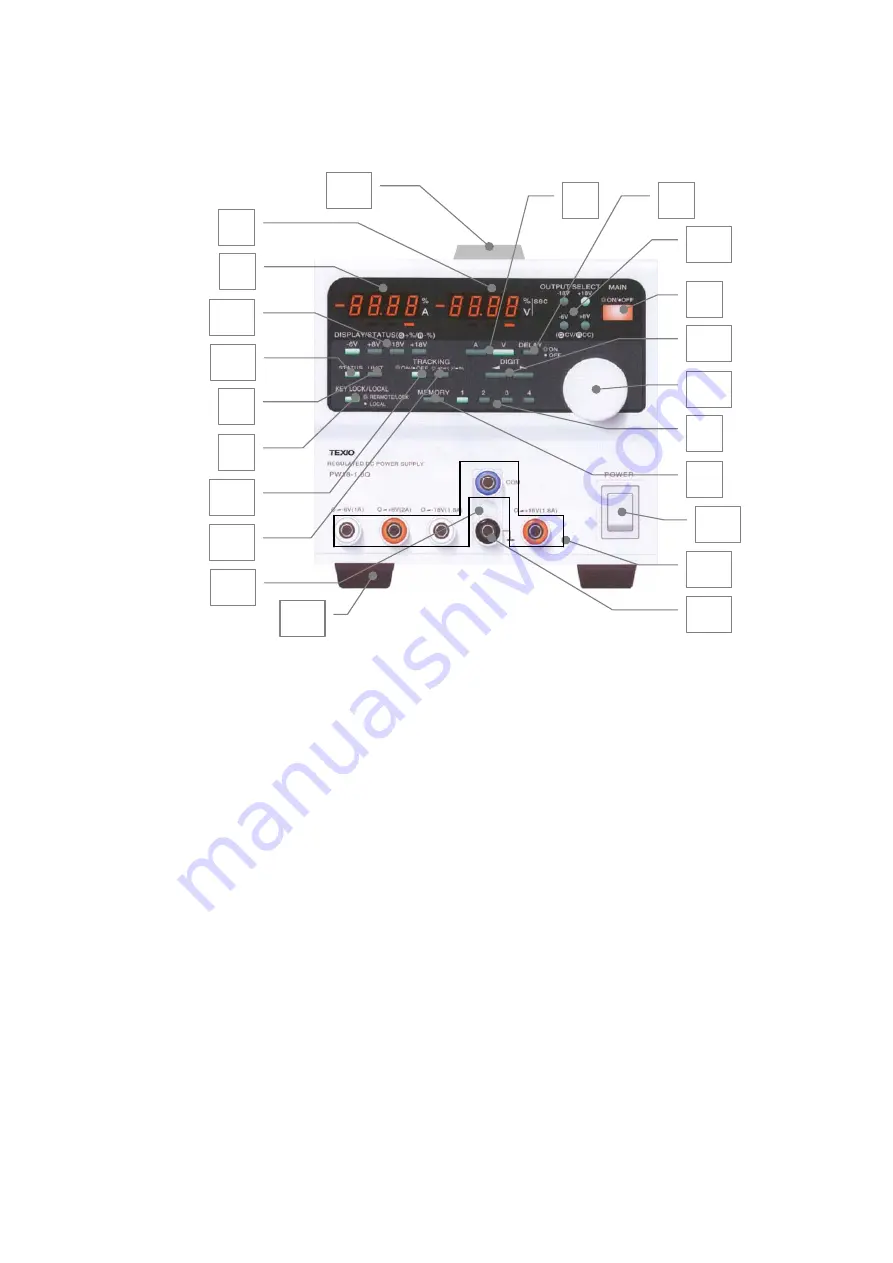
4. PANELS
4-1. Front Panel
□
1 Voltage indicator (4-digit red LEDs)
・
Indicates the set voltage, output voltage, tracking voltage percentage (%), delay time, PC address,
system address, and software versions of the PW-A series and IF-41GU, IF-41USB or IF-41RS
(option). The LEDs on the left of the 7-segment LEDs show the negative signs when negative
values are displayed.
・
The PC address, system address and software version of the IF-41GU, IF-41USB or IF-41RS are
displayed when the IF-41GU, IF-41USB or IF-41RS is used.
・
It is possible to change the value of a digit of the seven-segment LEDs indicated by a red LED
below it with the rotary encoder
□
16 .
□
2 Current indicator (4-digit red LEDs)
・
Indicates the set current, output current, percentage of the tracking current, delay, tracking, PC
address, system address, OHA alarm and Ear alarm. The LED on the left of the seven-segment
LEDs shows the minus sign and goes on when indicating a negative value.
・
The PC address or system address is displayed when the optional IF-41GU, IF41-RS or IF-41USB
is used.
・
It is possible to change the value of a digit of the seven-segment LEDs indicated by a red LED
below it with the rotary encoder
□
16 .
1
2
3
5
6
7
8
9
10
11
12
13
14
15
4
16
17
18
19
21
22
20
Fig. 1 Front Panel NOTE: The above figure shows the front panel of the PW18-1.8AQ.


