23
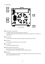
4-2. Rear Panel
□
23 Optional board mounting section
・
The optional remote control board is mounted in this section.
・
The PW-A power supply unit is supplied with a dummy panel mounted here if it incorporates no
optional board.
□
24 AC power inlet
・
Connect the AC power cable to this inlet to supply commercial AC power to the unit.
□
25 Fuse holder
・
There is a primary side protection fuse in the fuse holder.
□
26 Air outlet port
・
A fan exhausts air through this port.
□
27 External contact control connector J1
・
This connector is used for external contact control.
※
For details, see section "7. EXTERNAL CONTACT CONTROL" below.
□
28 GND screw
・
Connect a grounding wire to this screw if it is impossible to ground the PW-A series with the AC
power cable supplied with the product.
27
25
24
23
28
26
Fig. 2 Rear Panel


